About
After a couple experiments with vactrol-based dynamics and frequency processing, as well as a commercially released unit, i decided i have to learn how to do it right. Thing is, so far, all my vactrol drivers and ping circuits were not the best out there, and needed a rework. Also, although SFP35 works more or less as intended, i never got a steady filtery meow out of it. And so, after a bit of experimentation, this thing was made. This is Jelly VCF, named this way for being bouncy, wobbly and somewhat rubbery, too! Unlike my previous opto VCF takes, this one is a robust, calculated design that works optimally well for a vactrol-based thing. Its LED driver and ping circuit were majorly improved, so it behaves much, much better than its predecessors. It has the usual VCF controls: cutoff and peak (a.k.a. resonance) - each has a dedicated CV input with an attenuator.
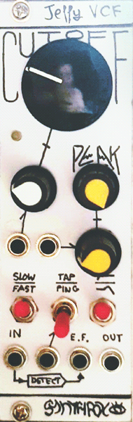
Below the 'classic' controls and their CVs are the three switches. The leftmost one has a descieving label: after making the panel, i decided to make that switch a three-position one. It switches between VCF (middle), LFF (up) and VCA (down) action. VCF mode is your usual audio VCF action. LFF, however, stands for "Low Frequency Filter" - this mode allows to use this module as a wicked, wobbly slew limiter for your CVs. In VCA mode, Jelly VCF's colour and resonance are almost completely taken away from the mix, and the module behaves much closer to a VCA, with only a slight tonal tilt.
The middle switch selects which way the module should be excited when a there is sharp upwards voltage transition on the associated input. "Ping" adds a short, decay-only envelope to the cutoff setting, while "tap" is mixed down with audio. Hence, "ping" is good for percussively opening up the cutoff setting while processing some audio, while "tap" is best when no audio is provided and the resonance is set to almost oscillate - the filter will then produce a short, pleasant drumlike sound.
The rightmost switch selects the filter's response curve - high pass or low pass. This is pretty self-explanatory. Low pass mode blocks away the entirety of the incoming signal when the cutoff is fully counterclockwise, but high pass mode doesn't reach high enough to make the trebles disappear into thin air.
Finally, down below are the four jacks. Left to right, they are: audio input, ping/tap excite input, envelope follower output and audio output. The built-in envelope follower always processes whatever is passed to the audio input jack - without the tap signal - and creates a CV representation of that audio's amplitude. This can be self-patched to either cutoff or resonance for envelope-filter style action, where the VCF dynamically responds to the input audio's volume.
All in all, this is a much higher quality design than my previous works, and i think i managed to nicely combine the classic general VCF control scheme and some personal weird ideas on what a filter could do.
Schematic
Schematic render without section dash-dot boxes available in the build resources archive
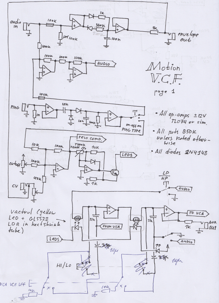
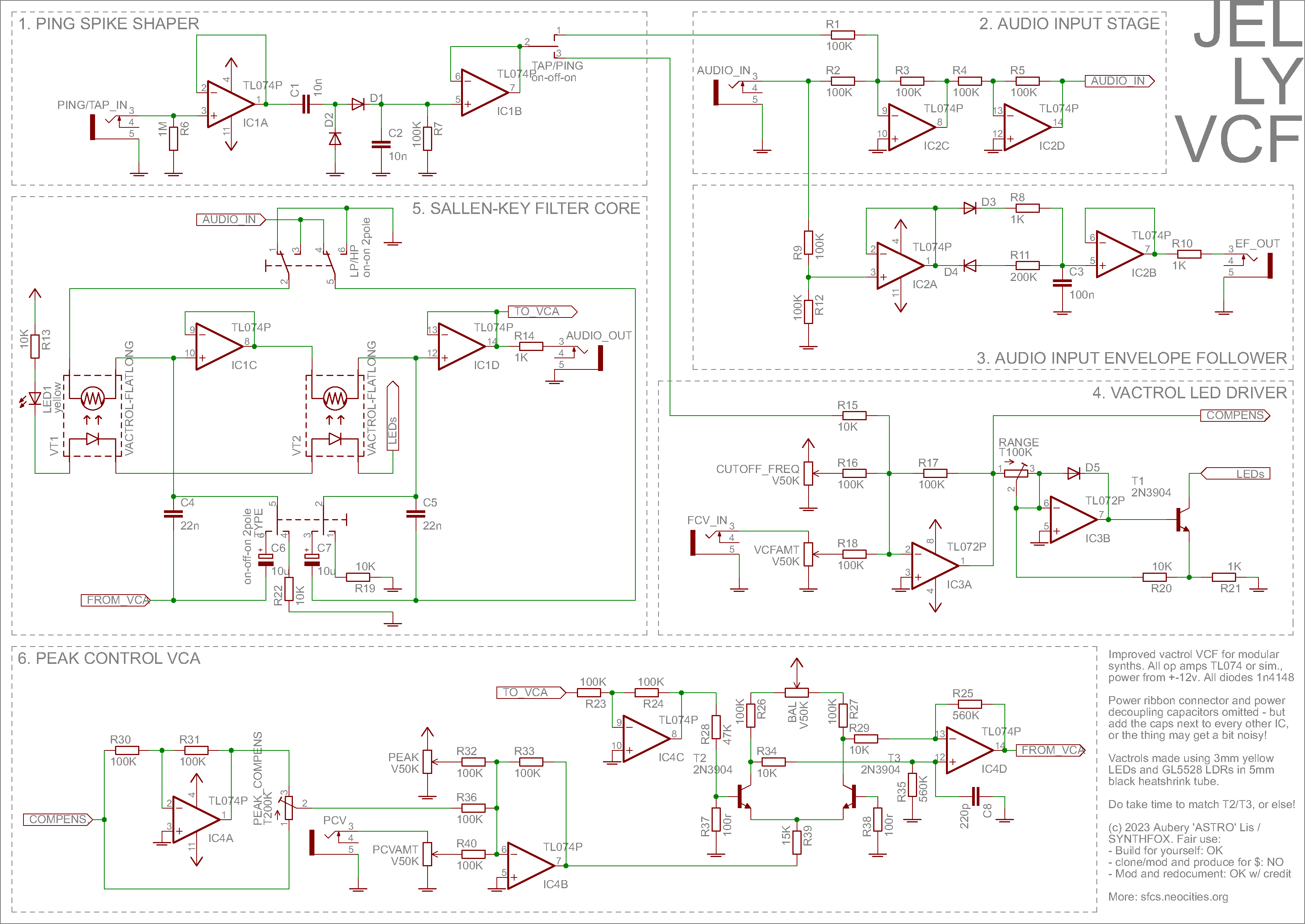
This filter is your usual, naive Sallen-Key topology implementation. The thing that gives it its character are the vactrols in that topology (duh!) and, well, the rest of the module! The schematic is split up into numbered modules, so i'm gonna go over each one in order.
First off, top left is a spike generator. It's kind of like a decay envelope, but way more organic; it detects sudden rises in voltages - like a gate, or an upwards step from a sample & hold - and generates a short, teeny spike. The bigger the input voltage step, the bigger the spike - likewise, the more pronounce is its impact on the filter. This part is an amalgam of my previous take on a ping input for an opto VCF, and an envelope for a cowbell by Elliot Williams, which, after an hour of experimentation, ended up basically a buffered version of what Elliot came up with. Elliot wrote up a nice what-how on this bit of circuitry, so, no need to re-type on my side; in essence, it's a high-pass filter action by C1 with a special diode setup that eats up the downwards-going spike. The positive spike quickly charges C2, which then slowly discharges through R7, regardless of what's going on to the left of C1. The result post-buffer is a short, sharp attack, followed by a fast, but smooth decay. The switch then sends this to mix down with the audio input (tap mode) or to the cutoff mixer (ping mode).
The audio mixer is your standard double-inverting summator using two op-amps and some 100K resistors. It is used to nicely add the tap spike to the input signal, without any crosstalk. Nothing too spectacular here. The section below it is an envelope follower: it detects the amplitude of the incoming signal and represents it as useful control voltage. It is based off your obvious slew limiter design - the easiest way to obtain a nice envelope follower. The design is a reduced form of SFP19. The potentiometers are replaced with resistors: a small one for rising time to have a sharp attack, and a bigger one for falling time, so that it keeps up with the mean amplitude instead of being a bad lowpass filter. The shape and range switches were also removed in favour of a nicely picked timing capacitor (C3). With it, the follower is pretty sharp, but slow enough to represent amplitude and not copy the signal, except in the lowest bass range. Keeping this envelope follower fast is important - it's gonna be primarily used on the filter's own cutoff, which is vactrol-based, and so adds some sloppiness to incoming CVs, which will make an already sloppy envelope follower straight up muddy in my taste. However, if one wishes to increase the envelope follower's response timing, it's easy to do by picking a bigger C3 (both rise and fall) or R11 (only fall time).
Below the envelope follower, under number 4, is the LED driver. IC3B is a current sink, and its main benefit is its much, much nicer voltage-to-brightness response when driving LEDs versus most other drivers that i've tried. In textbook applications, this sink is supposed to be controlled by a positive voltage to the non-inverting terminal, but i decided that it should be OK to use negative voltage to its inverting terminal instead. Hence, IC3A is an inverting summator for the initial cutoff setting, cutoff CV, and the ping spike - in case the ping/tap switch is set accordingly. It may so happen that IC3A produces a positive voltage; as a precaution, D5 is put in place to prevent op-amp from damage in case of a positive output from IC3A. This is done after applying the same logic as in electricdruid's vintage vca current source; ironically, i will never know if it does anything, cause if it does - it prevents the circuit from blowing up and letting me know it failed. Oh well!
Ok, now for the interesting parts. The filter core on the middle left is basically your average sallen-key filter with naive resonance, but also with a bunch of bells and whistles. First off, a two-pole switch on top changes the filter's response between low pass and high pass. It does so by connecting the buffered input audio from the audio input stage to the first vactrol's left leg and grounding C5 (lowpass), or grounding the vactrol and running audio into C5 (highpass). The switch simply sets which gets sound and which gets 0v. Next up is the two-pole, on-off-on mode switch down below: it sets the filter to operate in LFF (low frequency filter), VCF or VCA (or "colourless") mode. In the "off" position, none of those additional caps or resistors are in action, so essentially, the rest of the circuit only sees C4 and C5. Setting the switch left connects the big capacitors C6 and C7 parallel to C4 and C5 respectively, increasing the total capacitance, and hence significanly dropping the filter's frequency range. The filter cannot process sounds like this because it's too slow, but it becomes a great CV processor. On the other side of the switch are two 10K resistors that get snapped in parallel to C4/C5. These will add a frequency-agnostic path for the signal to take, diminishing the capacitors' filtering role and making the unit sound more like a VCA, although still with some remaining VCF colour with the resonance cranked up.
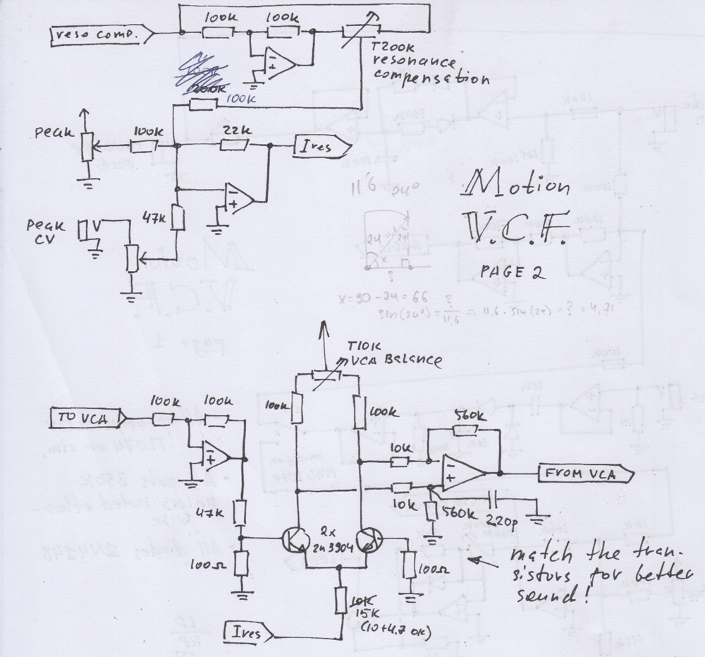
In many classic sallen-key VCFs peak (or resonance) is implemented with a simple voltage divider knob for manual control followed by an amplifier to introduce feedback to the circuit. In case of Jelly VCF, a discrete core VCA (IC4B/C/D) takes place of this knob, allowing for voltage control over filter's resonance. The VCA design is a derivative of my dual VCA with the same core: you can check in-depth info through that link. Since it's not used for precise CV manipulation here and a tiny bit of bleedthrough is a-ok, i threw out one unnecessary trimmer. Also, i replaced some resistors to better match the feedback levels that the filter circuit likes.
The final trick that this VCA allows is to make the resonance much, much more consistent over the whole cutoff range. Sallen-keys in general, and vactrol-based ones in particular, have that thing where if you set them to self-oscillation at a lower frequency, and then tune to a higher one, they would stop oscillating - meaning the circuit resonates worse the higher the frequency goes. This gets compensated by grabbing the inverted cutoff CV-sum from IC3A, un-inverting it over IC4A, and running it through a trimpot to add to the resonance level mix. Setting the trimmer correctly causes the resonance setting to get some additional kick as you turn the cutoff up, resulting in the filter nicely oscillating - or not oscillating - consistently over the entire sweep of the cutoff knob. C8 helps dampen the resonance at the most highest frequencies down a bit, since it tends to be a bit distorted/get too much kick from the compensation circuit when the cutoff is very high.
Calibraion:
- Start with cutoff fully counterclockwise and turn it clockwise. At some point, the LED will reach its brightness peak, and then suddenly go dim again. Use the RANGE trimmer to move the brightness peak to cutoff knob's full clockwise position.
- Set the resonance low, then crank it up just until self-oscillation at around 3000hz (you should hear a moderately high tone). Use the BAL trimmer to make this tone sound/look the closest to a sine you can. It will not be a nice sine, but this can help remove some nasty harmonics introduced by R27/R28 tolerance-based mismatch.
- Set the cutoff knob at around 9 o'clock, resonance low. Crank up the resonance just until the filter starts oscillating. Now bring up the cutoff frequency a bit. If the filter still oscillates, back down the PEAK_COMPENS trimpot to where it doesn't, and then back up until it just starts humming again.
- Repeat this process over a few moderate cutoff increments, until you reach nearly full clockwise. Verify that your filter enters oscillation reliably over the entire cutoff range. Then back down the resonance and verify that it doesn't spontaneously burst into resonance at higher frequencies. Adjust if needed.
- Once done, if using single-turn trimmers like myself, drop a tiny blot of nail polish on the trimmer's corner to gently fix its actuator to its body piece. This will help your calibrations survive a moderately shaky journey!
Note 16 nov 2023: for some reason, the ping circuit re-pings on downwards transition if this design is assembled out of SMD parts! I have no clue why. The thru-hole veroboard version works flawlessly. If you are experiencing double-pinging, replacing D2 with a 100K resistor helps.
Media
Basic lowpass and hipass sweeps with different resonance over a slightly non-ideal sawtooth.
Three similar little patch recordings concatenated into one demo. All use the excite input in PING mode to produce the percussive slap.
Envelope-filter action over an amen break amplified to eurorack signal level.
Using the unit as a CV processor to slew/woggle-ize some stepped random to control a VCO pair.
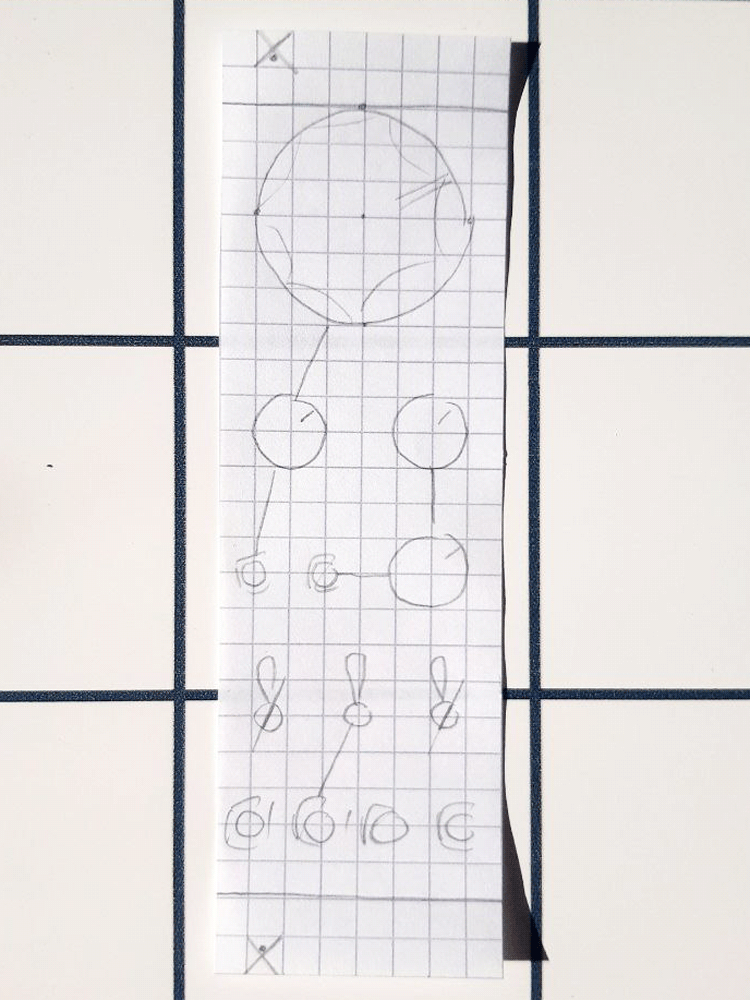
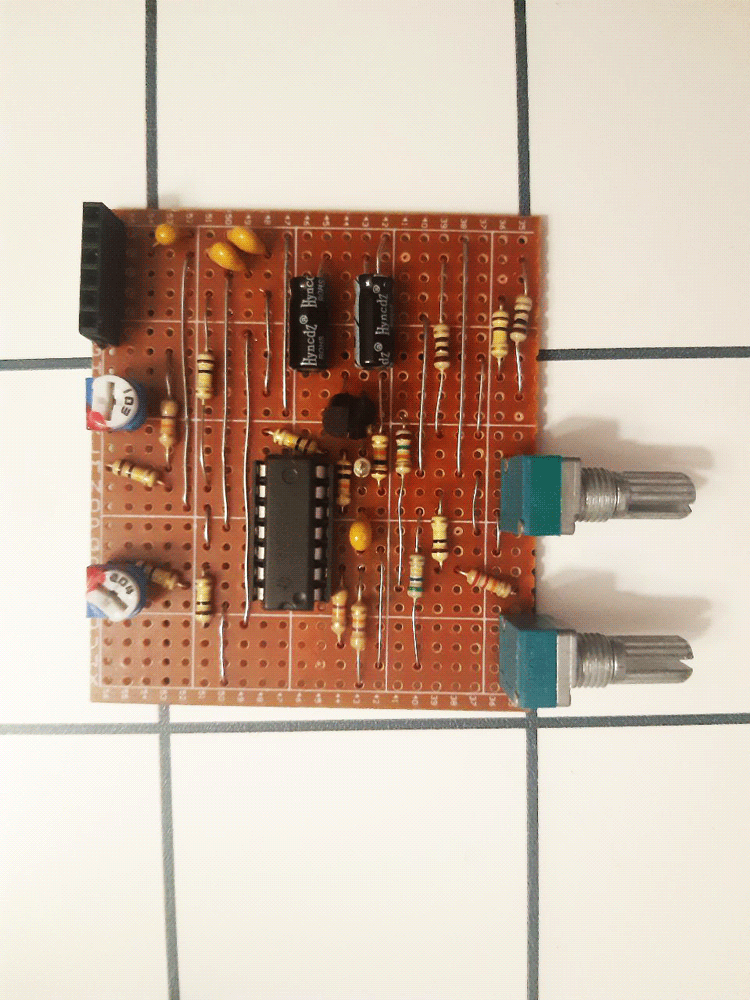
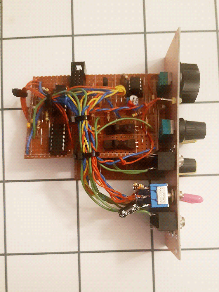
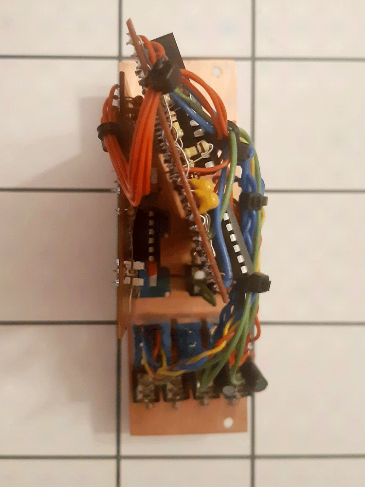
Pictures