About
This is another one of those 'Astro got themselves into trouble, intentionally' designs - an opto multimode voltage-controlled filter, or, Opto MMVCF. Although the name says "VCF", it is more of a.. squealy screamy equalizer-polarizer-counterphaser band-based mixer and also a bassdrum kind of a deal. If you're searching for a good VCF to build, go check Thomas Henry's VCF-1 and you won't miss. But if you're searching for trouble - you found it.
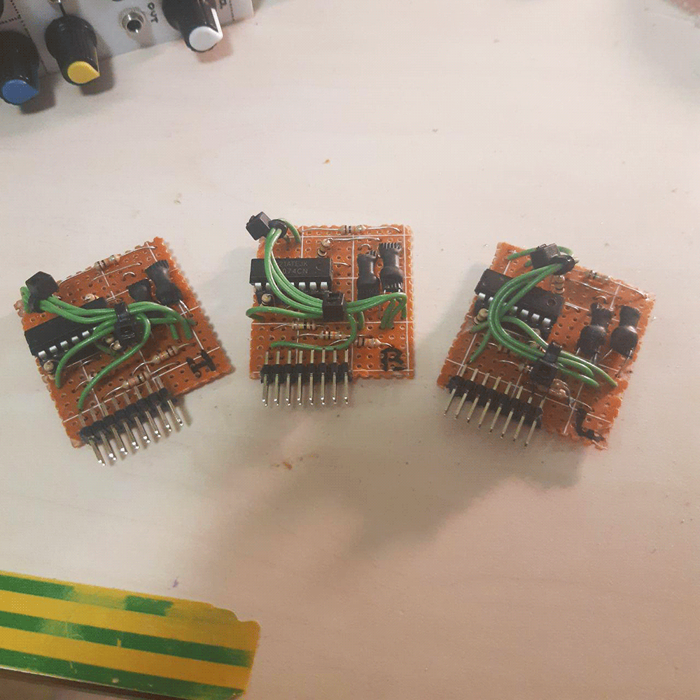
The filter follows a sallen-key lowpass topology and has three simultaneous inputs at the bottom - for lowpass, 'bandpass' and 'highpass' response. BP and HP are quoted because if you do all the nerding, you will find that they are not actually that in the equations; but they act close enough to be happy with them. Each input has a dedicated Thru-Zero VCA - that's what i call a very questionable opto sort of four quadrant multiplier circuit that i made. It works, but it's far from being precise. Both the filter core and the TZVCAs are made with vactrols - or, for nerds, resistive optocouples, hence the module name: the unit contains 8 vactrols total.
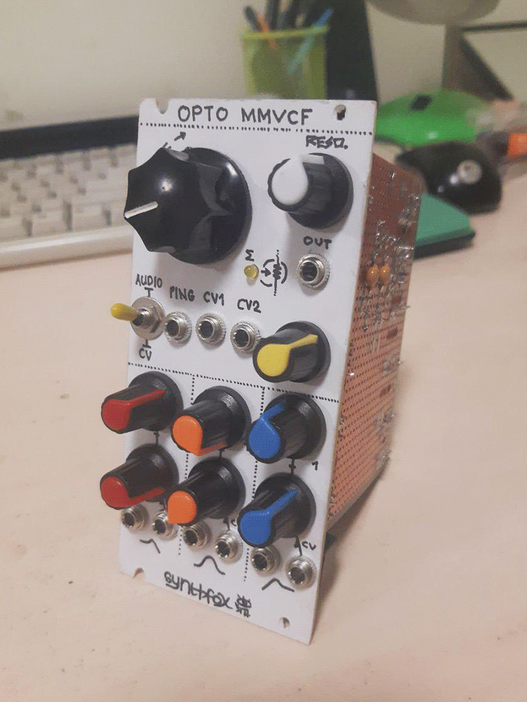
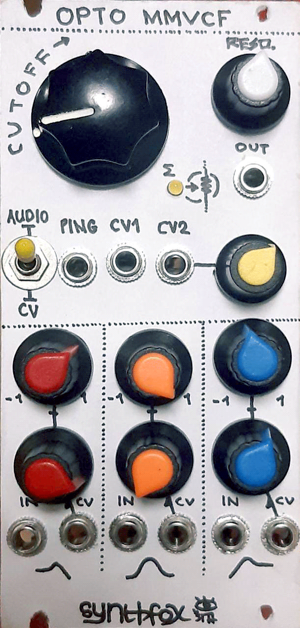
At the top, we have a big cutoff knob, as one should. Below it are the unattenuated CV1 and attenuated CV2 frequency control inputs. This filter can only dream of 1v/oct, so CV1 may as well be attenuated, if you're more generous with the faceplate space than i am. There's also a Ping input, which does exactly what you think it does: strikes the frequency control with a decay-only envelope and does the Vactrol Ring(tm). It expects a quick rise of voltage, such as the rising edge of a squarewave. It responds differently to rises of different amplitude, which is a nice expression tool. An LED shows the actual light level that's on the filter vactrols right now.
The RESO control is (duh) the resonance, which starts being loud at about halfways, and goes into weird territories as you proceed. It can be quite touchy, but this filter can do a gentle squelch, too - especially using the ping input. Finally the Audio/CV switch selects between the two cutoff frequency ranges: one is more suitable for audio, other can process CVs. The filter is not DC-decoupled and accepts any signals, so using it as a CV mixer/processor yeilds interesting results - such as 'woggling' around sharp edges of the CV and slew-limiting the signal.
I made better opto VCF design, so check it out if you want a more consistent filter action. The downside is it cannot take three inputs for three different responces at the same time, so, a bit less experimental.
Schematic
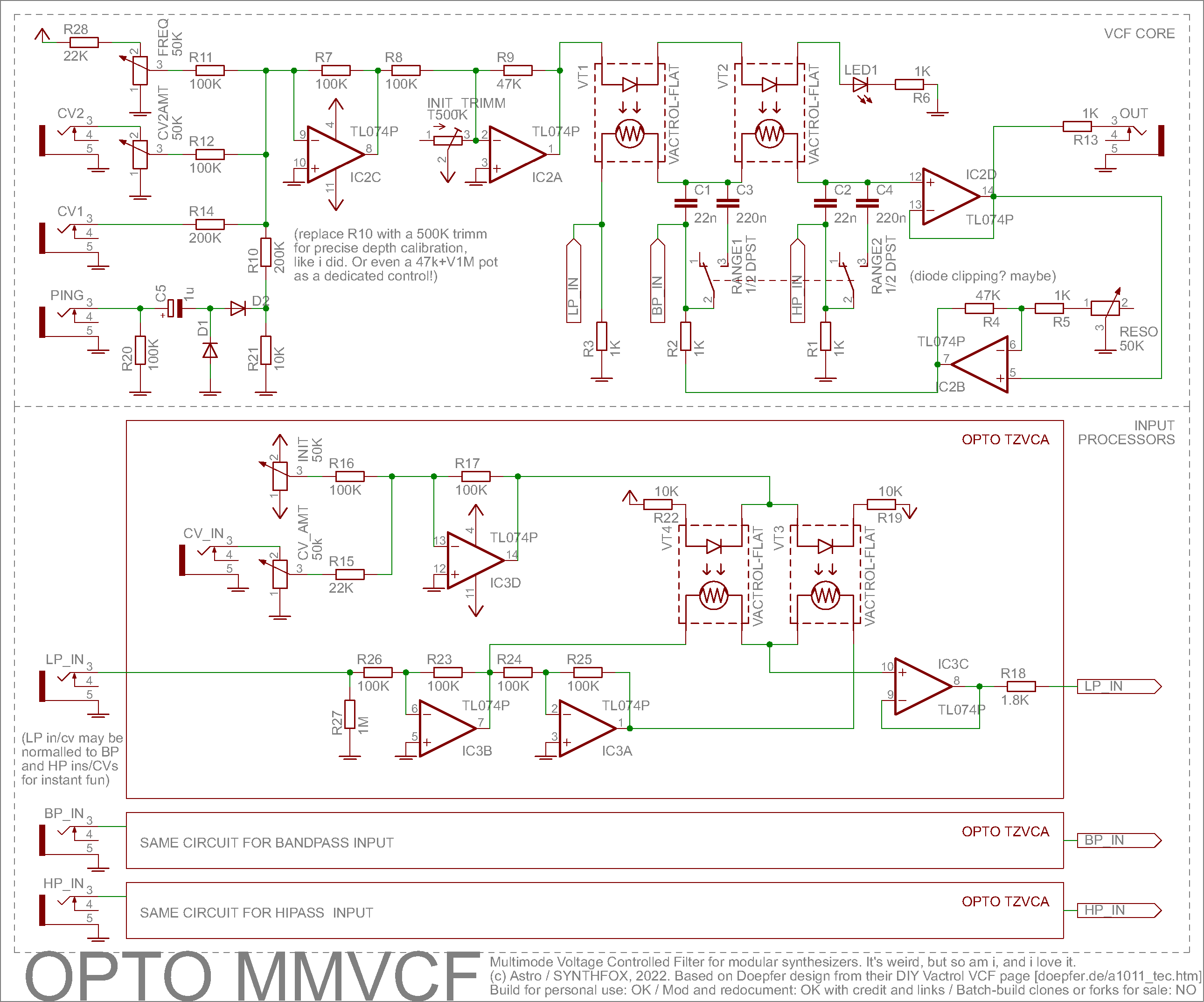
The design truly is a Frankenstein monster. It's based on the 'conceptual' description of a vactrol multimode filter by Doepfer, available at this page of theirs. It is a typical Sallen-Key filter, with the cutoff-setting resistors replaced with vactrols. It's a super lazy solution, but also an interesting one. More 'serious' sallen-keys use OTAs as voltage-controlled resistors, yet this method is expensive and space-consuming, and recently i've been having a terrible lucky streak of crap LM13700s, so vactrols it is. This topology is designed to be a lowpass, but it can be exploited in a smart way to have semi-true bandpass and hipass inputs: the Korg MS-20 filter does exactly that for the hipass, and everybody loves it. Explaining how a Sallen-Key lowpass filter works would take 3 pages of text, and i'm not exactly an expert on these (logic and sequencing are my upside), so i will leave this gap to you and duckduckgo/youtube to fill up, in case you're not sure about it.
The tricky part is getting the vactrol LED brightness control right. I use orange/yellow 3mm LEDs and GL5528 LDRs for my homebrew optocouples, and for three such LEDs in a row a 1K resistor seems OK. The INIT_TRIMM resistor sets the initial brightness: after you build and test the unit, set it so that the frequency knob starts lighting up the LEDs on its first ~10% of spin.
The range switch is also dead simple: it adds or removes big capacitors in parallel with the small ones in the filter core, dropping the cutoff range significantly. If you don't with for CV functionality, you can omit this mod - but then, it would also make sense to DC decouple inputs and the output (add 680n capacitors).
There is a couple less significant tweaks from the Doepfer variant, too. I split of the filter stages buffering op amp and the resonance op amp. This way, changing the resonance setting won't affect the amplitude of the output jack. However, resonance overrides the actual sound at some settings. I find this funny and nice, but for purists - maybe, adding another output option past IC2B may help. Also, the resonance amp's gain is set a bit differently: i found this to work better with a 50K pot for resonance, but at the end, it's still your usual non-inverting amp. Possible tweak: add counter-diodes around IC2B for cool nonlinearities and resonance taming, probably: even better if you can turn it on and off with a switch.
The Doepfer schematic general idea is to have a switch sending audio to either of the three inputs, but i thought it'd be interesting to experiment with sending different audio to different ins, or same audio, but with different amplitudes. This is where the second part of the Frankensteiner comes in - my own SFP22 Dual Crossfadeer. The core circuit of this design's TZVCA is identical to SFP22 - if you can't catch how it works by looking at it, follow the link. It's easy to convert it to a Thru-Zero VCA, as i call it to separate it from true four quadrant multipliers: if you crossfade from a signal to its inverted version using this circuit, they will cancel each other in the middle and be at their maximums at the sides. So all i did was invert the input signal, put it to the crossfader left side, invert it again (to get the initial input signal, but buffered at this point) and put it to the crossfader right side, and - there you have it: voltage-controlled volume knob which also inverts the signal on negative CV. It comes with a downside, of course - vactrols cannot go full audio range, so no funky ring modulator effects can be made with it, but hey: it's cheap and it (sorta) works!
By slapping such a TZVCA on each input, and then pointing them to respective points in the filter core, we now can dynamically mix audio with this thing. Better yet - if you normalize the LP input to BP and HP (or just use a mult and some patch cables), it can be an equalizer: LP, BP and HP become bass, emphasis and trebble. Use different audio per each input - and you get a mixer which also "fits" the audio in separate frequency bands. And, of course, territories of CV manipulation and feedback through other processors are endless.
Overall, this is not a hardcore or time-consuming build: i would recommend building this to someone who got comfortable with atari punk consoles and two op-amp lag processors, and is a great addition to a sound experimentalist's setup. But this thing should not be regarded as a true nice VCF: it's definitely a more experimental and effed up take on the matter. It leaves way more space for experimenting than the usual VCFs, but a nice resonant bandpass sweep is far from guaranteed.
Media
Basic sweeps with increasing resonance on each sweep with usual sawtooth to the LP input
Basic sweeps with increasing resonance on each sweep with usual sawtooth to the BP input
Basic sweeps with increasing resonance on each sweep with usual sawtooth to the HP input
FM trianglish tone to all ins at once, LFO swings the cutoff back and forth. Playing with levels of each input and couterphasing, as well as with the resonance, brings wicked results - not necessarily classic VCF type of stuff, but surely cool
Ping input demo - first in the Audio/high mode, then in CV/low mode.
This time, the unit is used to process a slow squarewave, and control a VCO with the result, first through LP, then BP, and finally the HP inputs. Note how LP keeps the squarewave, but slews/woggles its edges (resonance does that), BP only does the woggle, and HP does woggle and a sharp slap of what was the squarewave.
It's also a nice bassdrum
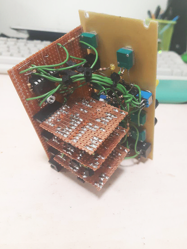
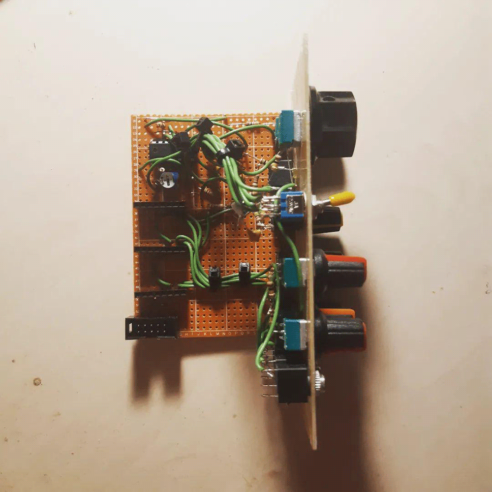
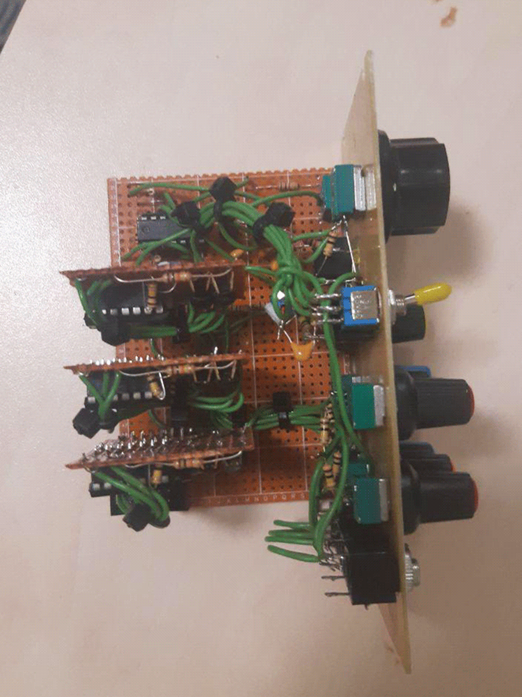
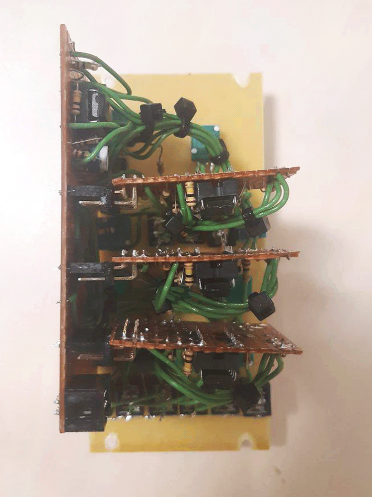
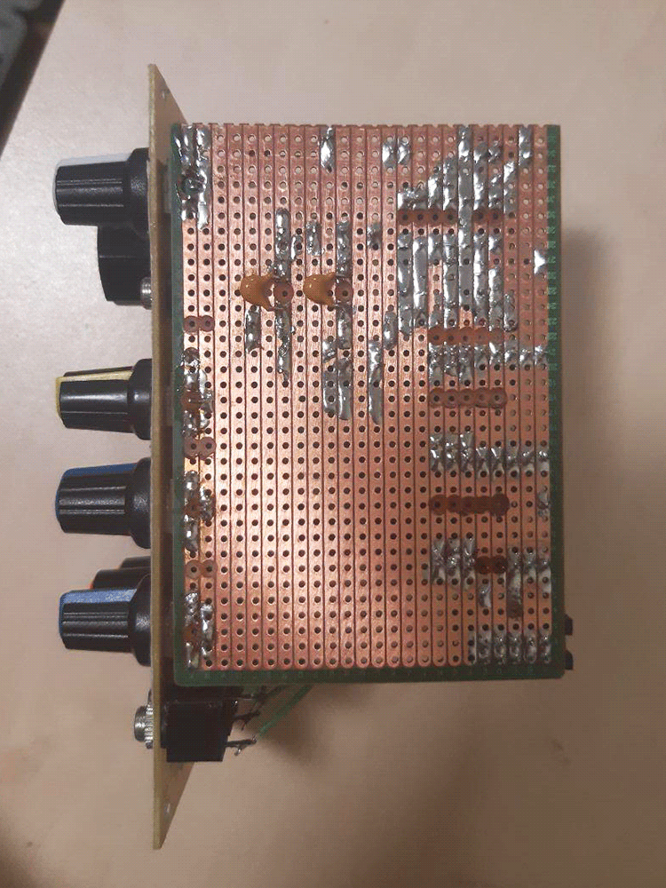
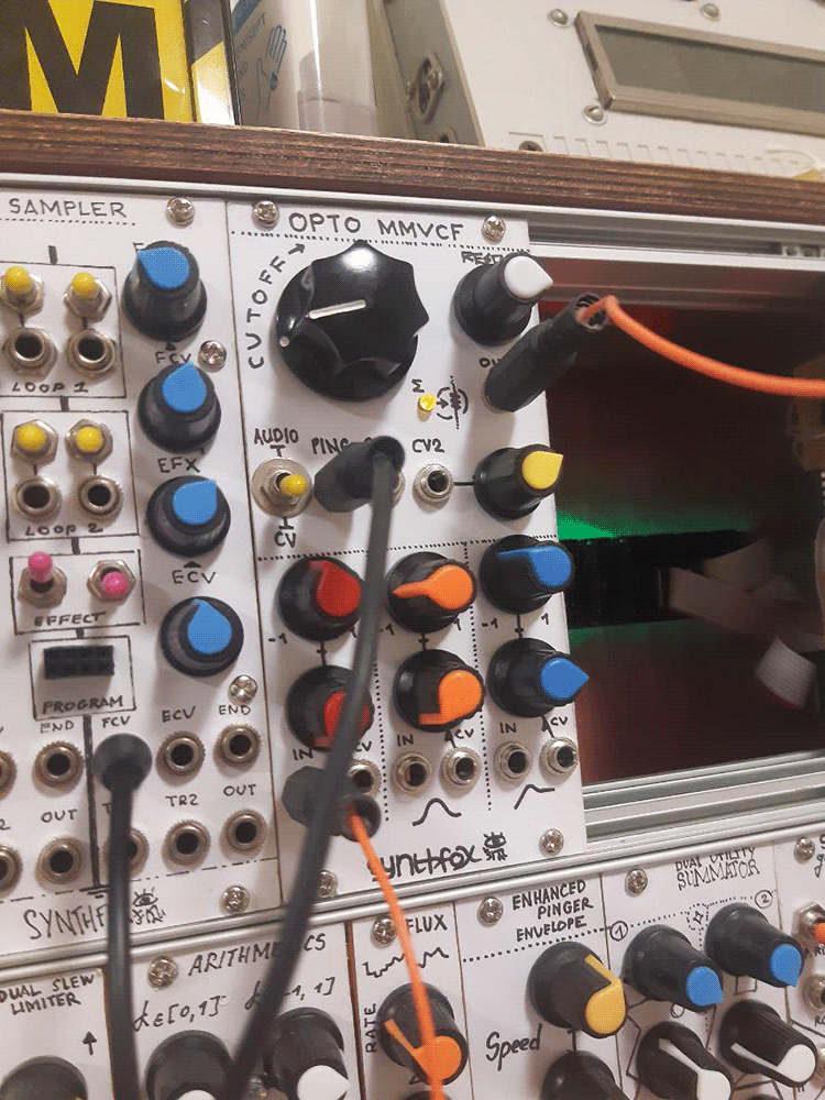
Pictures