About
Funnily enough, i have been in SDIY for more than 5 years, yet this is my first actual dedicated VCA module, and even now i built it not because i desperately needed VCAs, but because i was unhappy with the performance of the design used in Fluid Shape Complex VCO for modulation depth control. The old, 'classic' long tailed pair VCA design used is imperfect even if you match the transistors (which i did), at least for controlling a VCO frequency, as it generates weird, nonlinear DC offset as you open it. Naturally, the VCO (VCF, whatever else) drifts along with that. Although the mod depth VCA provides some tuning by design, i was unable to tune it to perfection. So i've been wondering - is it possible to improve that design so that it generates virtually no offset, while using the same architecture?
And, since you're reading this, the answer was "yes". This precision version of such VCA design can be tuned to having no offset detectable by human ear or my (crappy) measuring equpment. The drawback is, this design is also a fantastic thermometer, so the moment you take it away from your room, all the DC offset removing endeavours have a chance to shatter. This also means that the calibration process is hilariously stupid. So, of course, the word "precision" here is relative, as in, relatively to the design used for the SFP44 mod bridge. Probably, making The Usual OTA VCA will still be about the same precise or better, more temperature-resistant, and on top of that - with no need for careful tuning, while this circuit has 2 trimmers per VCA. However! As OTAs get more and more scarce, it makes sense to make a 'precise enough' design based on more common parts, which will last in production longer, and after they become obsolete, can be salvaged in feasible numbers. I wonder when a single transistor part will go out of production... anyways.
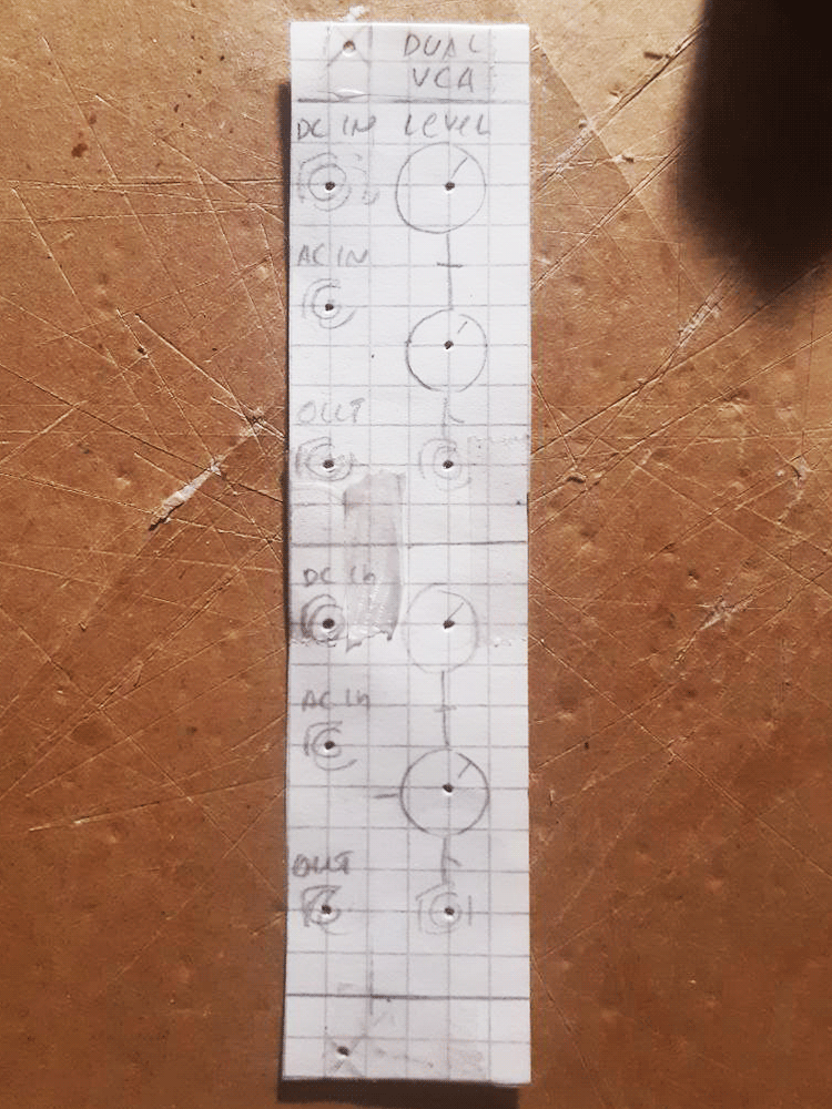
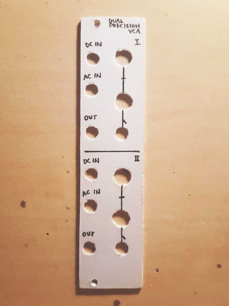
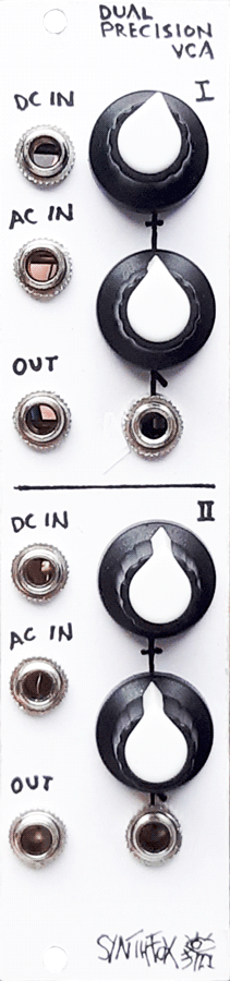
This module houses two VCA units. Each has a more or less familiar interface. Level control, level CV input with an attenuator, two inputs and output. The inputs are mixed together at equal volume, with the only difference being that AC input will filter out any DC bias or 'slow enough' DC (so, most CV signals) and is best used with sound, while DC input will gladly accept CVs, gates, and whatever else. The VCA itself is DC coupled, so, it can process DC signals just as nicely as AC ones. What, you wanted me to install a DC decoupling capacitor at the output? Then why was i going through the trouble of making the thing generate no DC offset by default, huh, smartpants?
A final little useful feature of the module is signal normalling. If the first VCA's output is not used and there's no patch cable put into the socket, then its output will get mixed in to the second VCA's output, and the mix of the two will appear on the lower VCA out. So, this ultimately becomes a 2-channel VCA-mixer, if needed. Handy!
In conclusion, this design is great, but probably still redundant while the OTAs are around. It is a flawlessly sterile sounding audio VCA with some overdrive capabilities on level fully CW and some positive CV on top. It is a really good DC processor, too, and technically is tunable to be flawless in terms of LTP-induced DC offset at the output. Practically, it really is not entirely stable in response ambient temperature, so it's probably not for use as a solution for super offset-sensitive applications in a live setup that you want to take to sweaty venues. However, it still is a good robust workhorse DC VCA, and even a precision one, if you go through the pain of nice calibration and keep it in your room, in the same exact spot of your rack box. If you don't want to have fun building, and just want a working baseline solution, use the OTA VCA design, which there are tons of laying around.
Schematic
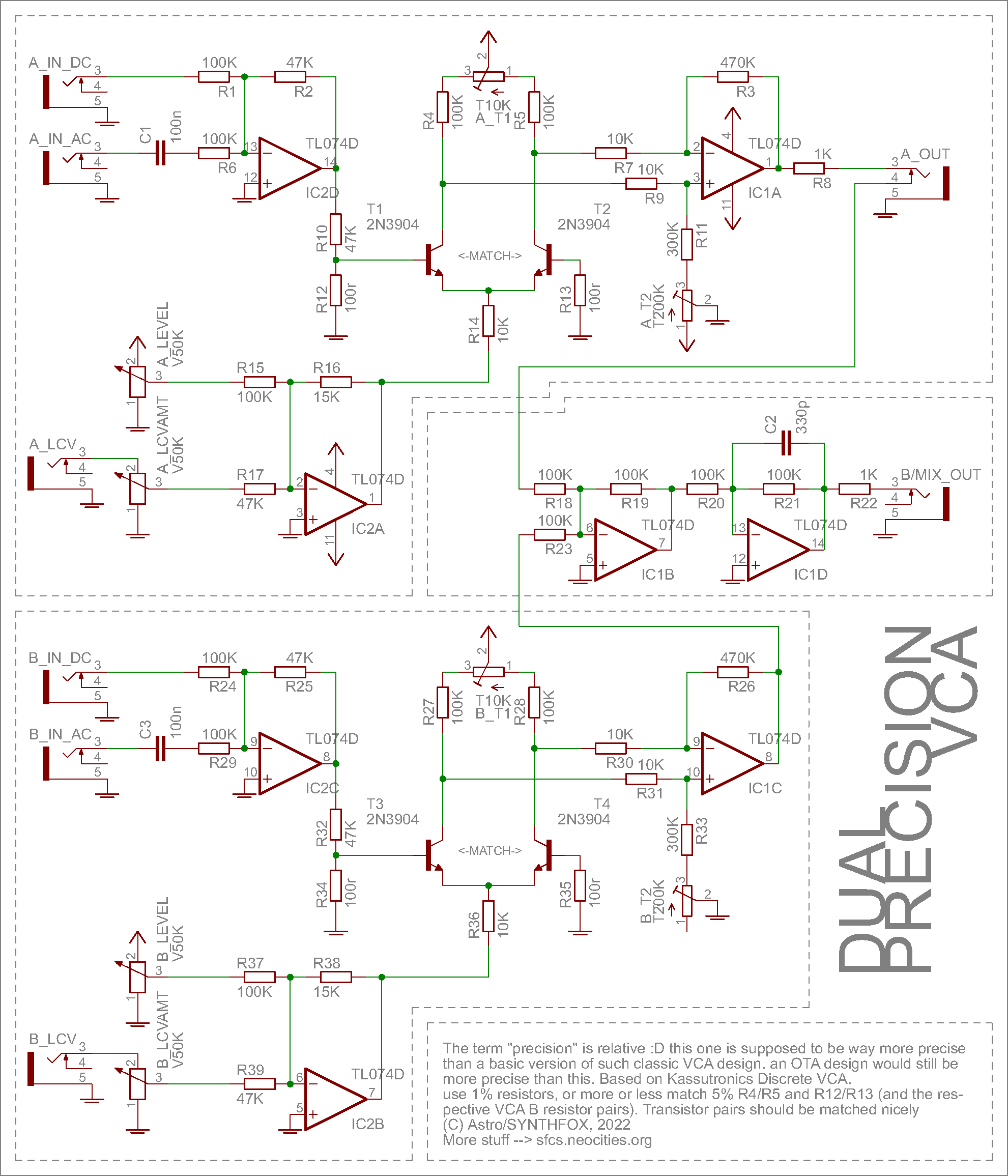
UPD 4 NOV 2022: IC1 had a missing power connection on the schematic (rails drawn around IC1A). Fixed.
The schematic is based on a classic long-tailed-pair VCA design. Some of the designs that use a similar approach are Kassutronics Discrete VCA, Yusynth Simple VCA and Klein Mortiz' Classic Transistor VCA, among many others. Kassutronics' webpage entry describes how it works in nice detail and with some simple math. Still, i will overview the VCA action briefly using the VCA on the top of the circuit diagram as an example.
The input of the module are two jacks without volume controls, one is DC coupled, the other is DC decoupled (or AC coupled, if you must). They are invert-summed over IC2D. Note that R2 is 47K for 0.5 gain, instead of 100K for unity gain. This is to avoid clipping even if both inputs are really loud.
The core of this VCA design is a long tailed pair (LTP) - a transistor setup like T1/T2. One transistor has a signal going into it, divided by about 500 with the R10/R12 voltage divider. The other is grounded through 100r (improves dc response). Changing the voltage on T1 base changes the current through it (makes it easier or harder for it to pass), thus changing the voltage drop between the collector and the 100K resistor R4 above it. This tiny difference of voltage drops after R4 and R5 is decoded into a non-differential (simple usual) signal form and amplified by IC1A. Note how the T1-R4 junction goes to IC1A + input, whereas the T2-R5 junction is connected to IC1A - input. This is opposite to all the designs i've seen so far, and that's because the LTP itself is an inverting amplifier, and usually they use the op-amp to un-invert the signal. However, we already inverted our inputs by summing them over IC2D, so the LTP inversion is actually nice in this case, and we don't need to un-invert it. This VCA core, and it has 2 trimpots. These are to tune the unit to near-zero DC offset over the entire level knob range.
Speaking of which, the unit has two knobs. The level control, and the level CV input amount control. They are invert-summed over IC2A. The resistors are picked so that CV input can be amplified about 2 times if needed, while the level knob covers the entire range of amplification from 0 to about unity gain. The output of this op-amp provides current to the LTP, controlling the overall gain of this amplifier. I'm still a bit confused, despite having an understanding of what's going on, but it works.
The other VCA is absolutely identical, so, no point in describing it. The only major difference is that the upper VCA has its output going to a jack A_OUT through the R8 output impedance (don't omit output impedances!), while the lower VCA's output goes through R23 to a standard double-inverting summator of IC1B/D and appears at B/MIX_OUT jack. This summator handles the mixing-in of the upper VCA output if nothing is inserted into the A_OUT socket. C2 is installed to smooth out the pops, if very sharp CVs are used, but does so very gently and does not remove important audio frequencies.
Calibration:
- Verify that both halves work at least *somewhat* and indeed only need to be calibrated to work as intended
- Put the module into the rack (without screwing it in), turn it on for 10 minutes
- Put the upper VCA output to a VCO with a sensitive frequency CV input, such as 1V/O input or a CV input with attenuator full CW
- Move the level knob of the VCA. The VCO should drift, as the VCA generates DC offset.
- Set the level knob full clockwise. Tune trimmer T1 so that the VCO frequency is the same if you plug and unplug the cable from its CV input (or memorize the frequency, but this is prone to generate mistakes).
- Set the level knob full counterclockwise. Tune trimmer T2 like T1 in the previous step.
- Set the level knob full clockwise. You should be getting some, although less, offset. Repeat steps 5-6 until you get no detectable offset over the entire turn of the level knob.
- Install the module into the rack, let run for 1-2 minutes. Verify that the DC offset is still in the range you are happy with. Adjust trimpots slightly if needed - i did this with the module still mounted in the rack.
I advise putting the module back into the rack for 10-15 seconds after each trimmer adjustment, as it will require different tuning for the temperature inside and outside of the rack, at least in case you have a linear PSU inside the box, like i do. I probably should not have done that.
Media
DC offset test. One VCA was tuned so well that it generates absolutely no offset. The other generates slight offset that is audable to a keen listener, but that is OK with me.
Two decay envelopes pinging two triangle oscillations, the results are mixed internally and are taken from lower VCA's output. This demo was recorded before the anti-pop capacitor was installed; it gently muffles down the pops generated by the sharp decay envelopes.
DC modulations (audio-rate oscillation and stepped random) are controlled in magnitude with a sequencer and an envelope respectively and mixed using the internal mix-in feature, then passed to a VCO.
An enhanced version of the second demo patch. These VCAs sound very clean - even somewhat too sterile.
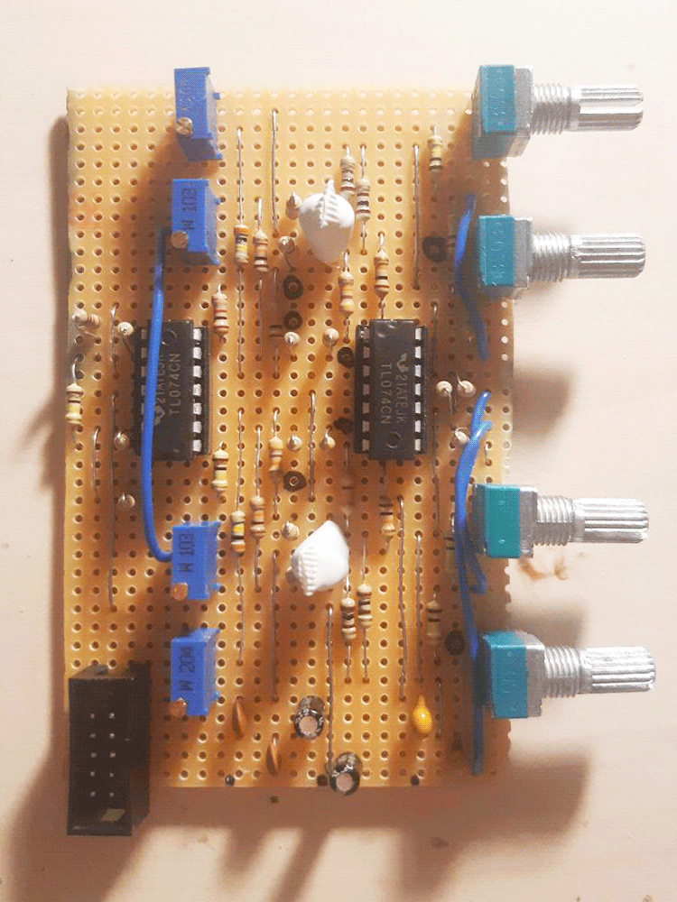
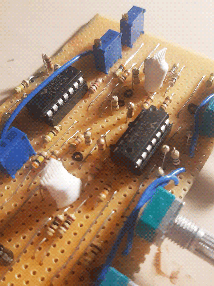
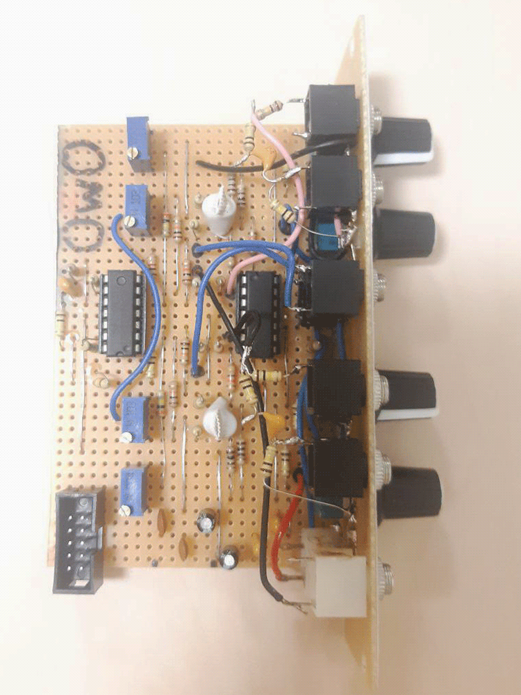
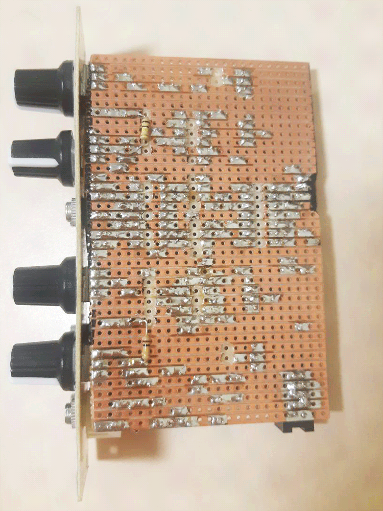
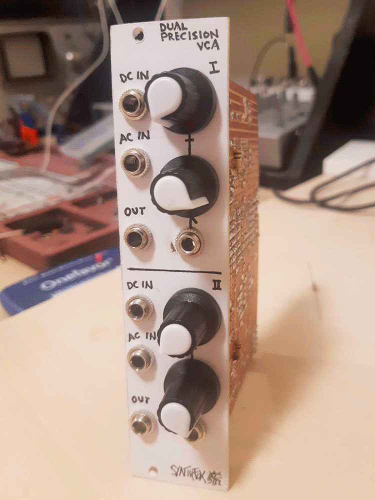
Pictures