About
Shaping Gate is a nifty combination of a vactrol LPG-like volume control circuit and a transistor waveshaper/wavefolder, that allows you to at the same time manipulate the volume and the timbral characteristics of sound. It's really easy to make for experienced builders, and not that hard for the newcomers, so if you have some sound source like a VCO and a control voltage source, such as an envelope or an LFO, this is something that will enhance your system's possibilities without that much of hard work.
UPDATED 19 NOV 2020: this module went crazy half a year ago and i was postponing the revival, but i finally did it, and now it's a solid build. I also noticed that the shaper circuit i actually built was far from the one i drew on the original schematic - which is a copy of the Lockhart Wavefolder, or Simple Wavefolder of Ken Stone's. My apologies! The Lockhart Wavefolder soudns great, but for some reason it also passes a ton of 50HZ and noise to the output for me, so i sketched up a transistor new, very similar transistor shaper/mangler circuit, and it works/sounds just fine. Check out the updated schematic!
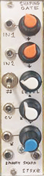
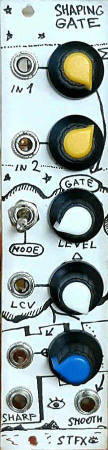
Left is the original faceplate. Right is the refaced, rebuilt unit.
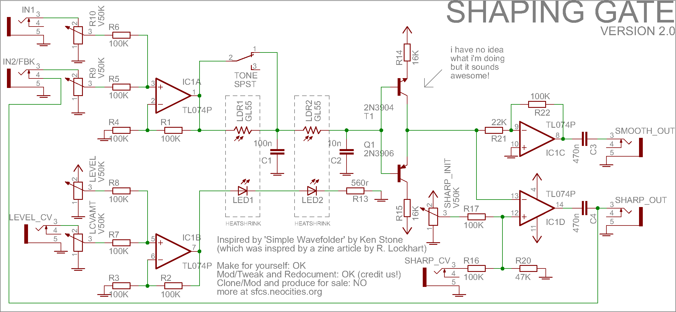
Schematic
Below is the schematic for my Shaping Gate. The schem is very simple and can be built around just one quad op amp on a veroboard - that's what i did, took me about two hours. The vactrols are made out of GL55 (preferably 5528) light dependant resistors and orange/red LEDs and work just fine this way. The top op amp is a non-inverting audio mixer, right below it is the same circuit for mixing a CV input and a voltage coming from the initial gain setting pot. Next the mixed-down audio is passed through two LDRs (one of them, with a bigger filtering cap afterwards, can be cut off with a swith for a brighter sounding, but less VCA'ish application) and goes to a waveshaper. The LDRs are affected by the LEDs controlled by the output of the CV mixer. Very simple.
After the vactrols, the audio goes to a shaper and then from the shaper's output, two outputs are formed. One (called 'smooth') is just an amplified version of the signal. Note that if you use a different shaper, you may want to change the value of feedback resistor around the op amp to adjust for its volume drop. The second signal output is called 'sharp' and it's basically a voltage comparator that outputs -12 volts if the shaper's output voltage is above the set threshold and +12 if it is below. The threshold can be modulated with an external CV input, thus some cool PWMish sounds can be achieved.
Another cool hack is to patch the sharp input into the module's own input and mix it with an incoming sound. It brings some weird crunchy emphasis to the sound. Also, it can act as an annoying high pitch VCO this way! In a pinch, the circuit can be used to mix down and modulate CV's, since there is no decoupling capacitors in the signal path.
Possible modifications:
-Make both inputs have attenuators (done on the schem below for some reason, i have the second input unattenuated)
-Have diodes replaced to some weird diodes you found in an old radio or something
-Change the diode clipping pair's ground to a CV and see what happens
If you do these mods and find cool results, or find some other cool mods, be sure to tell me!
Media
- 00:00 Doepfer A-110 sine -> Shaping Gate smooth out, LFOs on level CV
- 00:37 Two doepfer A-110 sine outs mixed down. Manual up-down turning of level
- 01:02 Same as above, but with the switch in up position, cutting off one LDR
- 01:16 Sine wave to one audio in, Sharp out feedback to second. Funny emphasis
- 01:52 Annoying high pitch feedback oscillations
- this demo is of the old design, and differs from what it sounds now slightly. most sound features are still the same, though!