About
Dual Pluck Envelope is two envelope generators in one panel, with the only control available being decay (and its associated CV input attenuator). Seems puny? Take your words back! Such envelope is the heart of all krell ambient patches that we all know and love, but also a clock, an out of the box percussion envelope, a sawtooth LFO, a gate to trigger converter, and maybe something else.
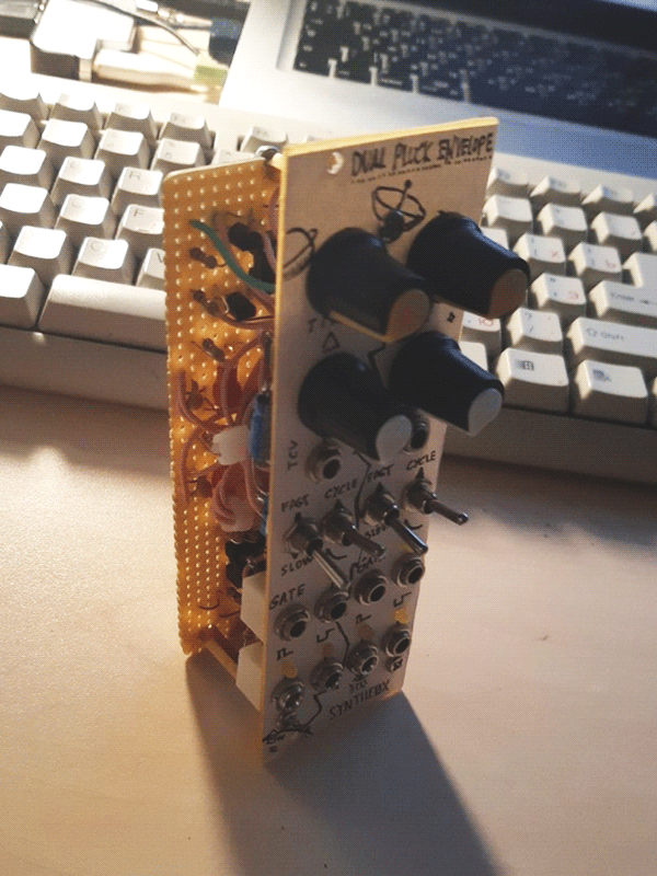
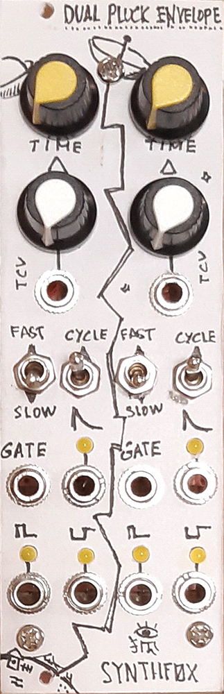
The only two available control knobs are time (the more clockwise the faster it gets) and time CV amount, with a dedicated CV input jack below. Even more below it are the two switches - one for toggling fast and slow range of decays, and the other for cycling it. Then it has a gate input - the circuit has an associated comparator section for it, so it can be triggered by any signal, including, for instance, the other pluck envelope's output. To the right of it, there's the main output of the module - the decay-only 'pluck' envelope. Finally, below those there's a trigger output which outputs a short pulse whenever the circuit detects a gate at the input, and the end output which lights up when the decay of the envelope nearly finished - patching it to gate input is generally equivalent to toggling the cycle switch.
Such an envelope is very important for drum patches as an instant and animatable percussion envelope, as well as to many other things in modular. A very similar module is the 208's Pulser section, but of course my schematic is created by me and has its own weird quirks instead of the 208 pulser's. I decided to use yellow knobs for time settings to honour the 208's Pulser, though, because it's probably my favourite CV section of that synthesizer.
[NOTE!] the circuit behaves weirdly for me once in a blue moon, especially with timing caps smaller than 1 uF. It most likely is because i made it of sketchy trash parts and soldered it on flux not meant to be used with circuit boards (and any copper at all), which brought a ton of problems and hours of cleaning and scrubbing. The circuit seems to be fine, but it may and most likely is far from perfect. It works 99.9% of the time, so i encourage you to build it, but be aware that it may show some character, and if you happen to find out why - please, don't hesitate to tell me!
UPD 31 OCT 2021: i designed a much, MUCH better decay envelope generator. You can still build this one if you wish, though.
UPD 25 NOV 2022: and for a design almost 1-to-1 in functions to this one, but made with like 60% less parts, no vactrols (good in this case) and better stability, check this build out. Really, the SFP17 dual pluck envelope feels very outdated at this point, and more of a museum exposition now. You can still build it or get inspired, though, who am i to stop you?
Schematic
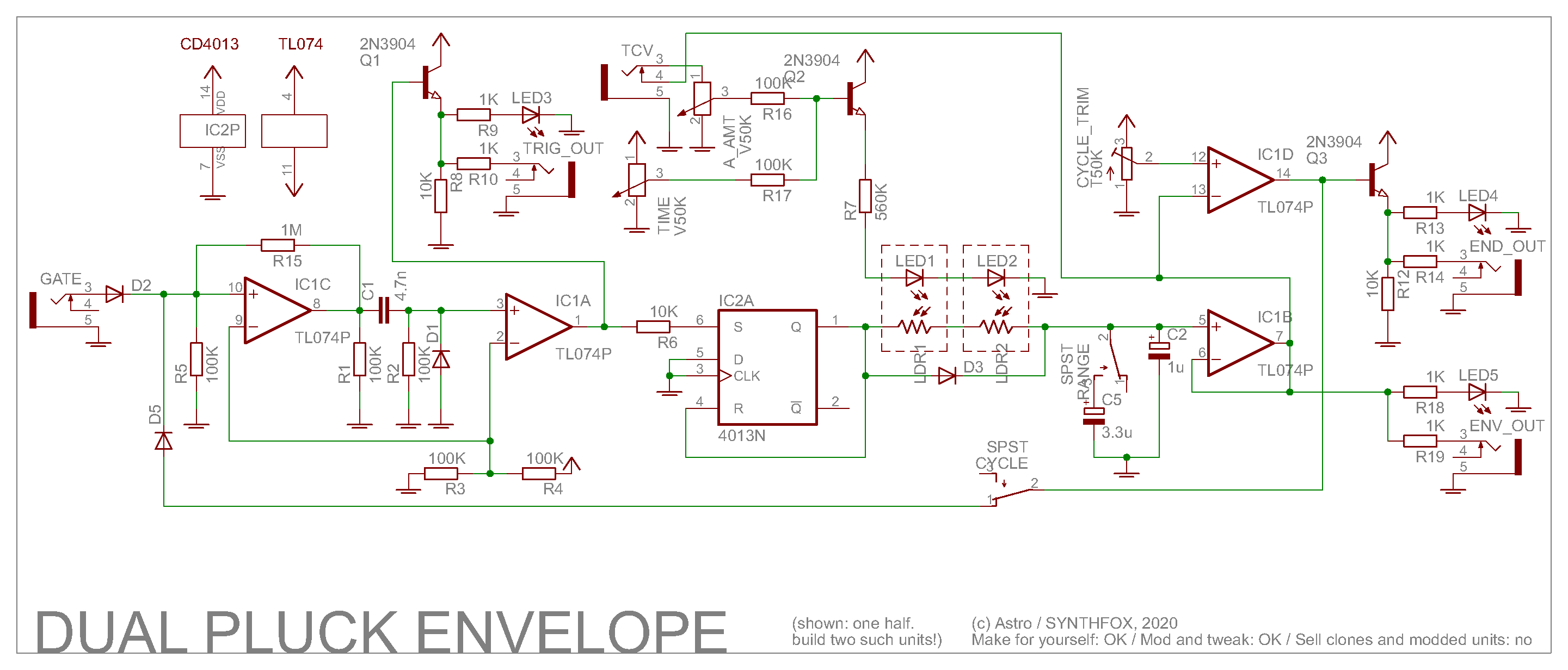
All my schematic descriptions start with this, but... the circuit is really simple! Really though, if you think of it, it can be broken down to 3 parts: gate processor, slew limiter and output processor.
Gate processor is made around first two op amps IC1C and IC1A - first one compares the incoming gate signal with 1/11 VCC, then this sharp signal is passed through a capacitor C1, which converts it to a positive spike when the comparator output goes high, and a negative spike when the comparator output goes low. The negative spike is put to ground through D1, and the positive one is yet again compared with 1/11 VCC to convert it to a sharp rectangular pulse. I then used 1/2 of CD4013 to... do some magick with it. It shifts the level from -12/12 to 0/12, and does some other magical thing (probably inserts a puny propagation delay, or something) that makes the thing cyclable: without it, the envelope works just fine when gated, but barfs itself when you feed the end of decay output to the gate input. The output of the comparator is also buffered through a simple common-emmitter transistor buffer for the trigger out. That's pretty much it about the gate processor stage.
Next up is a "will do" vactrol slew limtier, probably featured in at least 2 more modules of mine. It's two light dependant reistors (i prefer GL-5528) instead of a potentiometer, and two LEDs (bright matte orange ones work fine for me) driven by the sum of time setting and time CV, which get summed by Q2. Time CV input has the envelope output normalized into it - basically without anything, it becomes a shape control. In most cases, turning the knob up will make the envelope more exponential. D3 goes around the two LDRs to skip them when charging the capacitor(s) at IC1B voltage repeater's non-inverting input: charging happens almost instantly, and the discharge happens through the LDRs, hence takes (variable, VCable) time. C2 is a 'fast' capacitor, i say have it more than 1 uF, but you can experiment around: smaller ones will work, but will do strange things when you cycle the envelope. C5 is an additional capacitor which gets added up to C2 if the switch conducts, making both minimal and maximal decay longer. 3.3u is a fine value that brings the overall capacitance to 4.3u, and bings very long decays. Don't go too big, because it may mess with stray resistance of traces, etc - the cap still takes time to charge, and at some point the length of the pulse provoded by our gate processor won't be long enough to pump the cap fully.
Finally, after the IC1B buffer, we have the output section. Envelope output jack and control LED, and a comparator around IC1D, which tells if the envelope has gone below a voltage set by trimm resistor. The output is buffered with a transistor and goes to the output jack/LED for the end of decay output, and also is connected back to the diode OR at the gate processor section input through a cycle enabling switch. To tune this trimm resistor, turn both potentiometers down (get the envelope to be the slowest possible), then turn the trimmer until the end of decay LED turns on. If it's already on, then work the trimmer to turn it off, then go back to just the position when it's steadily on again. If you built two, you can run both comparators from the same trimmer, just make sure to trim it so both LEDs turn on when envelopes are at rest.
I decided to make it dual because i didn't want to leave one side of the CD4013 unused, but you totally can build a single one, add some modifications, and whatnot. Have fun!
demo patch: the SFP11 Shift Core Generator is ran by the same clock that triggers one of the envelopes, and provides random length for the envelope's decay, as well as random pitch for the VCO pair. Envelope opens an LPG the VCO pair is put through.
Another demo patch - now the envelope is cycled and its length is constanly dragged around by a random voltage fluctuation. Its trigger output is triggering a sample n hold with noise as the input, generating a random voltage on every envelope's hit. The envelope opens an LPG for a VCO, that is controlled by the sample n hold's random voltage output. Quick and dirty krell patch!
Very simple way to create complicated rhythms: using envelope outputs to CV each other, and trigger outputs to trigger the percussive sounds. A ton of different rhythms emerge by just turning the knobs!
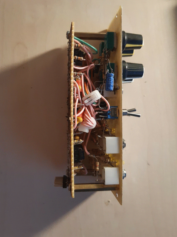
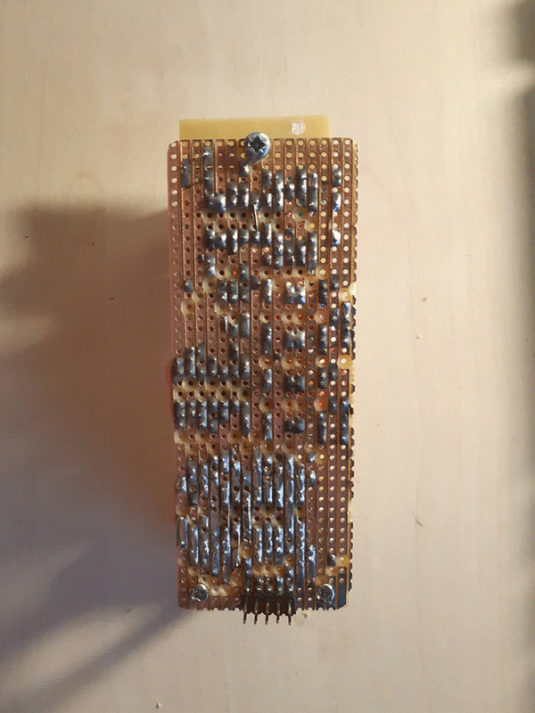
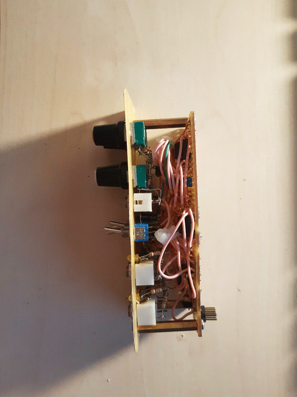
Pictures