About
I wanted to make more enhanced pinger envelopes, as i felt like i lack decay envelopes in my life. However, it dawned on me that i would mostly use them as percussive envelope sources, and not as the other 80% of that fancy design's applications. So i thought - why not to think up a dirt cheap, way simpler, yet more or less reliable decay envelope circuit that fits this exact application instantly? And, well, here it is! Four of them, to be exact, because more drums. The four units on this module do the exact same thing: generate a decay-only envelope.
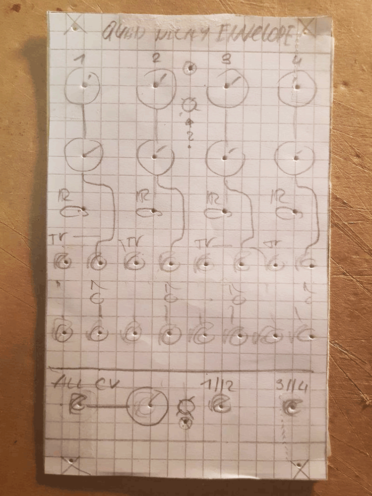
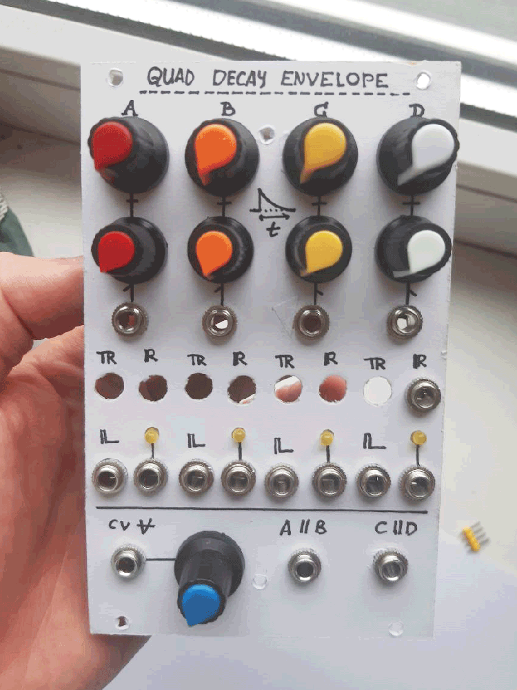
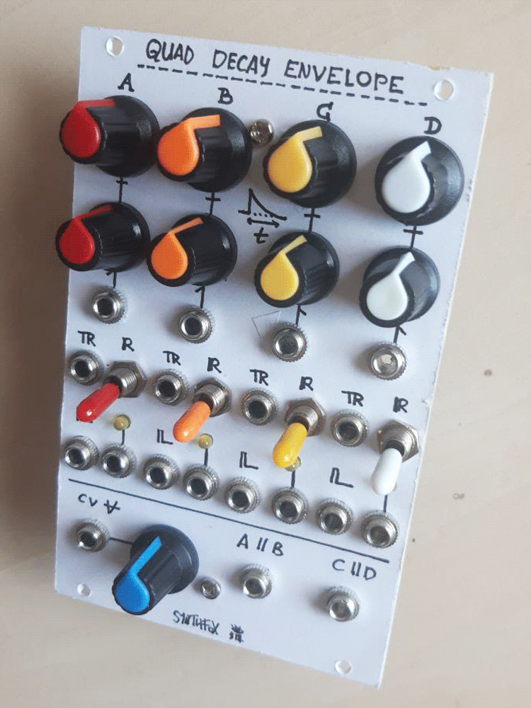
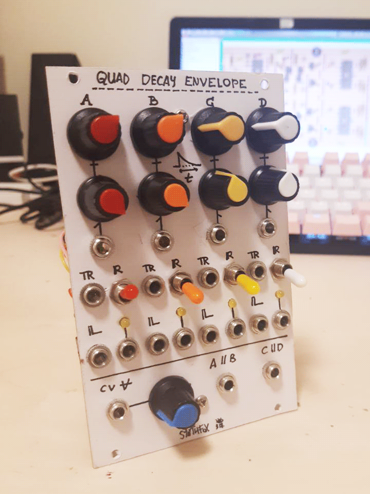
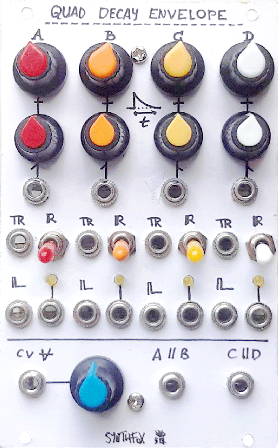
Each envelope generator has a decay time knob with a dedicated attenuated decay time CV input. The decay range varies from a few dozen milliseconds to a couple seconds. Each env has a gate/trigger input 'TR' (duh!) - anything can be used as a gate source, as these are fit with comparators. The envelope will be retriggered if a new gate is detected while the envelope is still doing the decay. The 'R'(ange) switch selects between normal (lower position) and very short (upper) decay range, the latter being efficient with sharp percussive sounds. Each envelope has a trig output, providing a short 12v pulse each time a gate at the 'TR' input is detected, and the actual envelope output, fit with an indicator LED.
Below the individual controls of each envelope are master control elements. The CV All attenuated input is added to all four decay controls simultaneously, making for an instant control over the entire module. +12V is normalled into its jack, so the knob acts like a "master decay time" if nothing is patched in. The A||B and C||D outputs are the respective envelopes OR'd, as in, the maximal of the two wins. This works nice when triggering one envelope slightly after the other, or having them run completely independently.
The part count for this module is laughably small, while the resulting range is, while not as crazy as the pinger's, totally sufficient for percussive sounds and so on. It comes with a few drawbacks, such as the envelope shape isn't exactly linear or exponential, and is somewhat related to the selected decay time, or the (in my case) 200mv negative offset on the trigger outputs, which is not a big deal, but it should not be there. But aside from those minor things, it works very well, and serves as a robust choice for its indended applications, saving me the enhanced pinger for crazier things.
Schematic
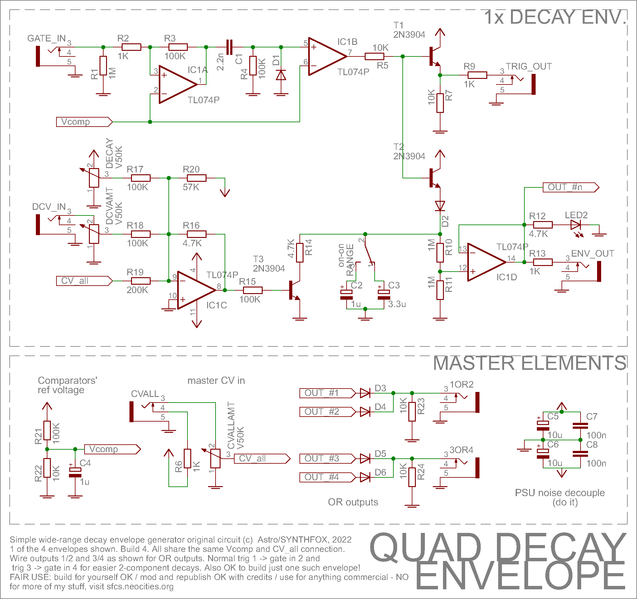
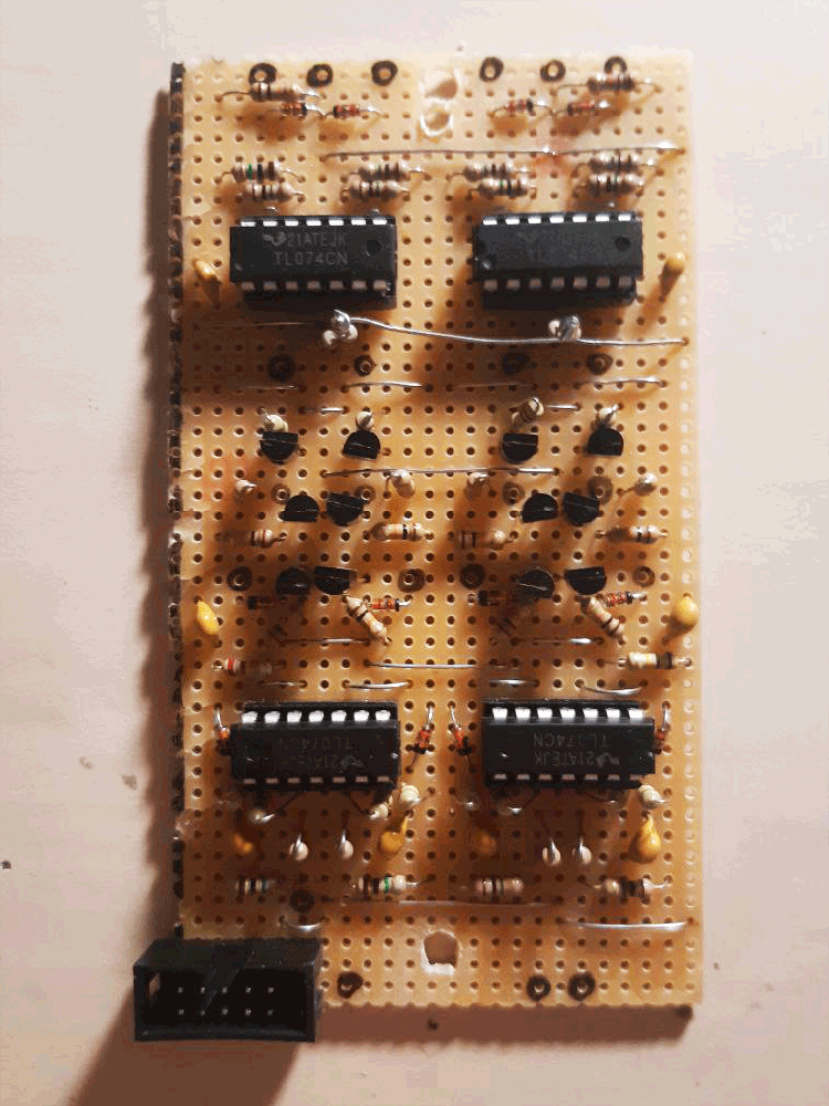
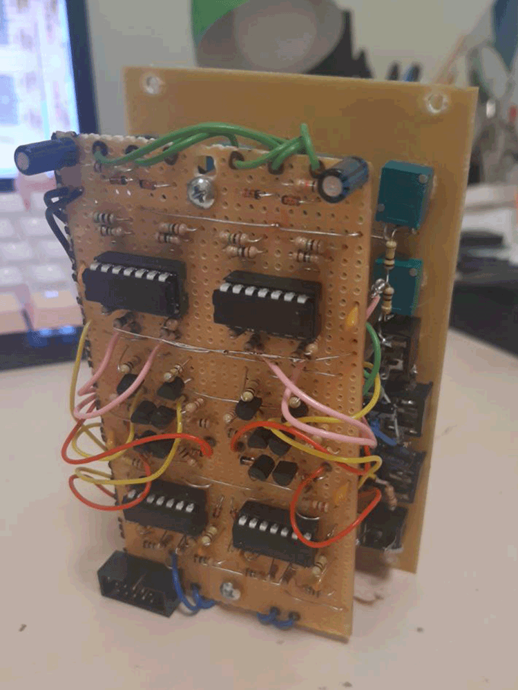
This decay envelope design was aimed to be simple and fast to assemble, so a single envelope requires just a few common parts. In fact, one envelope uses one full TL074 quad op amp and three 2N3904 NPN transistors. I encourage you to build four (cause it's fun) but you can also build just one and be happy with it. It is worth noting that with simplicity of the build come the drawbacks: this circuit's behaviour is far from perfect in many ways. But hell if i care, it's so easy to make nice soundin' drums using it with some VCAs and sound sources!
IC1A/B are a gate to trigger converter. Both are set up as non-inverting comparators, both comparing against Vcomp set by R21/R22 to about 1V. IC1A converts any input into a nice rectangular signal, so that any signal (e.g. LFO, noise, sound, other envelope) can be used as gate, not only dedicated gate/logic signals. R2/R3 make the IC1A comparator have a bit of hysteresis for improved stability. After IC1A, the detected gate is turned into trigger by first shaping it into a spike with R4/C1/D1, then detecting it and converting it into a nice sharp pulse with IC1B.
T1 is a simple transistor buffer for the short trigger pulse derived by IC1A/B. Supposedly, it also converts the IC1B +12/-12 rail to rail output to a 0v/12v gate, but for for some reason - god knows why - in my build all four of these output about 200mV negative instead of precisely 0 in my case. These are logic type outputs that don't really get any use outside of that, so i don't care that much, as most of my modules' gate inputs are equipped with comparators. But this is something worth noting. To be fair, my 2N3904s came from a sketchy vendor for a weird price, so i may be getting karma right now.
The short pulse from IC1B opens T2, which instantly charges the capacitor C2 or C3 through D2. The capacitors are then discharged through T3 and R10/R11. For some (yet again unknown to my pea brain) reason, the spike generated on C2 (or C3) this way appears to be taller than 12V, judging by IC1D clipping one third of the envelope against the positive supply rail if it tries repeating the spike before the R10/R11 divider. So, R10/R11 fit the envelope inside the supply voltage range, so that IC1D can nicely buffer it to the output jack without clipping.
The decay time is controlled by varying the voltage at T3 base. IC1C is a summator that does a funky shenanigan. It is built on top of a usual inverting summator design. However, i (experimentally) found that T3 base has to be driven from about ~0.7v to ~1.6v (or something like that) in order for the decay range to be even and not have dead zones at the lower or upper part of the decay knob's rotation. Below 0.7v (or something), T3 is turned off - probably because of the sillicone semiconductor magick - and the discharge only happens through R10/R11 (2M total, very slow). As voltage at T3 base rises, the envelope decay time shortens. But after more than 1.6v (or something) on its base, T3 doesn't make the envelope any shorter. For this reason, the IC1C inverting summator, which would otherwise output 0...-12V as you turn the decay knob clockwise, is augmented. R16 is 4.7K instead of the usual 100K (which would be unity gain), so the gain of the amp is about 1/20. R20 adds negative offset to the inputs, providing positive offset at the output, because IC1C is an inverting summator. This way, the decay knob swings the IC1C output almost exactly inside the "nice, varying decay times" region.
It's worth noting that at the lowest time settings, which is when the decay knob is full CCW, the envelope shape is visibly exponential, while as you make it longer by turning the decay knob clockwise, it becomes more and more linear-ish, but not exactly. Build a crap hacky circuit, get crap hacky envelope shapes! But what is the SDIY charm, if not this?
Finally, at the bottom of the schematic are some funky things in case you plan building four identical envelopes in one panel, as i did. If you don't: coward. Anyways, R21/R22 set the comparator threshold for all 8 comparators (IC1A/IC1B, for each env). It is not necessary to make a separate divider for each env, but it is good tone to add C4 to assure it is stable and unbothered. The CVALL input/knob is basically a shortcut to controlling all the decays at once, which sometimes is a lot of fun, and can be very expressive. Note how it connects through a separate R19 to EACH copy of the envelope: that is, a 200K resistor to each summing node, not one 200K and then it shorts all the summing nodes. There's also the '1 OR 2' and '3 OR 4' outputs, which are simple passive diode ORs of the respective decay envelopes. Can be fun if you trigger the envelopes at different rates, or trigger one with a slighd delay after the other. And don't forget the power noise decoupling magic capacitors to keep your PSU happy!
Media
A simple fm pair -> VCA drum, ruled by 2 decay envelopes: 1 for frequency, 1 for volume. Showcasing the range by playing with the controls manually.
A sequencer triggers envelopes A and B in a pattern, and A||B out opens a noise hi-hat. Note how i can dial in the 'open' and 'closed' hat lenghts independently and have no need to summate them before using on the VCA, as the OR input already does that (and is even better for this purpose). Another envelope, gated on each clock pulse, opens the bassline filter.
A chaotic patch with all four envelopes triggered seemingly randomly. A||B controls the FM garbage drum, while C controls noisy drum and D controls filter drum. With a turn of the master knob, i can drive this patch from crackles to full on percussive blasting, and inbetween.
A full demo patch with some generative CV over decay times, etc.
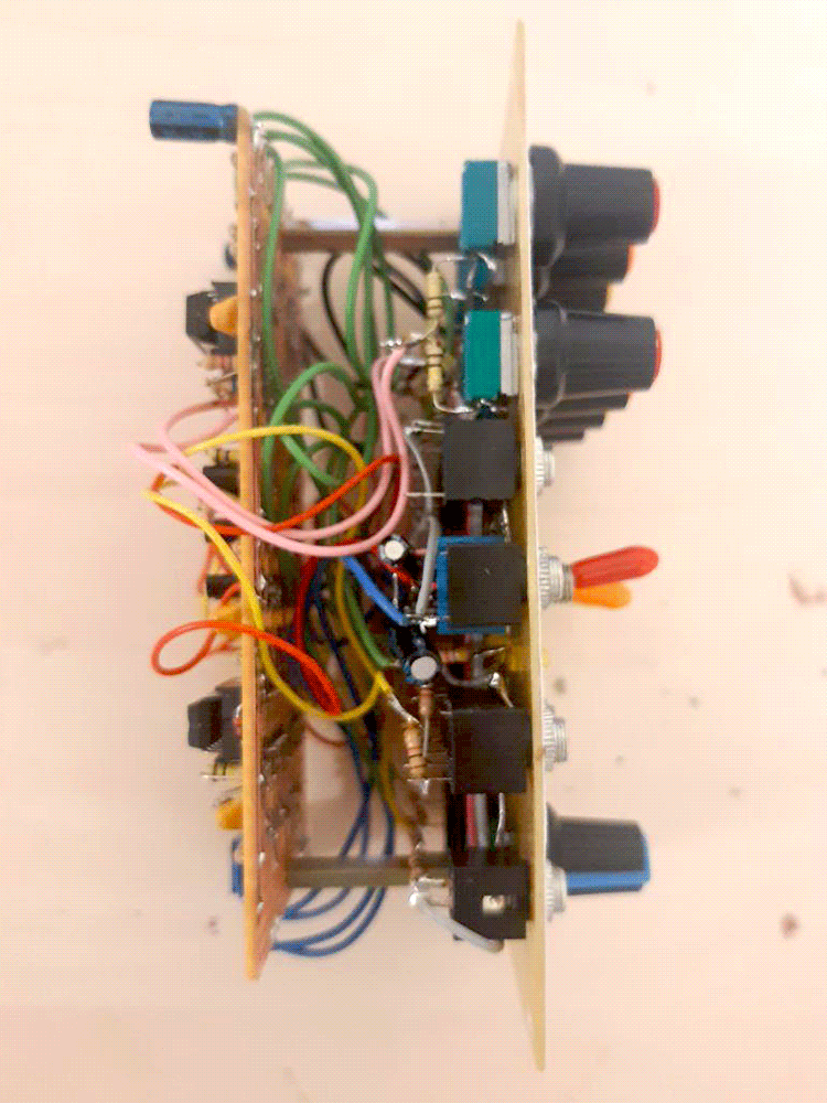
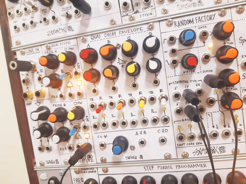
Pictures