About
Following my previous more general module, the Dual Lag Processor, this module is a dedicated envelope generator. Inspired by the Pulser of the Buchla 208, this envelope generates a function that instantly rises to its peak, and then falls down in set time. The "pinger" part of the name is a throwback to Pulser, and so is the yellow knob colour, but the module itself far exceeds the abilities of the Buchla submodule. It also is a replacement for the Pluck Envelope Generators, another Pulser-inspired, but vactrol-based module, which is just a bit too quirky and useless for its part count.
The core of it is a Serge VCS, stripped down even more after being minimized already for the Lag Processor. The range of possible decay times is immense, and time is selected with the Time knob and the Time CV attenuated input. There also is a shape control, which morphs the function's "bend" from outwards (logarithmic curve) to none (linear) to inwards (exponential curve). This setting notably affects the decay time, too - logarithmic curve is slower and exponential curve is faster than linear. Usually, the curve would be set somewhere between linear and exponential, so the timing parts were optimized for that.
The input logic of the module is a bit tricky, but is very useful and can all be used at the same time. There are two main gate/trigger inputs: Trig and Async. Both have comparators behind them, and will gladly process continuous signals, e.g. LFOs. They do the same thing: launch the envelope. However, the Trig input only works if the previous envelope finished its decay and is laying flat. The Async input, however, will instantly produce another spike at any given time. The Cycle input and switch both set the envelope to cycle, with an external signal or manually, respectively. Finally, the Inject input injects (duh) a signal right into the slewing core of the module, along with the logic-generated spikes, and this way, the module can be used as a weird filter or negative-only slew: good old Sergesque "this thing is anything".
Finally, the module has three outputs: normal envelope, inverted envelope and start spike. The inverted envelope is inverted around 0v, so it starts at a negative point and reaches 0v from below. The start spike outputs a very short spike every time a Trig input trigger or a Cycle retrigger succeeds: you can clock stuff with it. The module is pretty stable if calibrated precisely (get a multiturn trimmer!) and will even be a sawtooth (sub)VCO, if needed.
Schematic
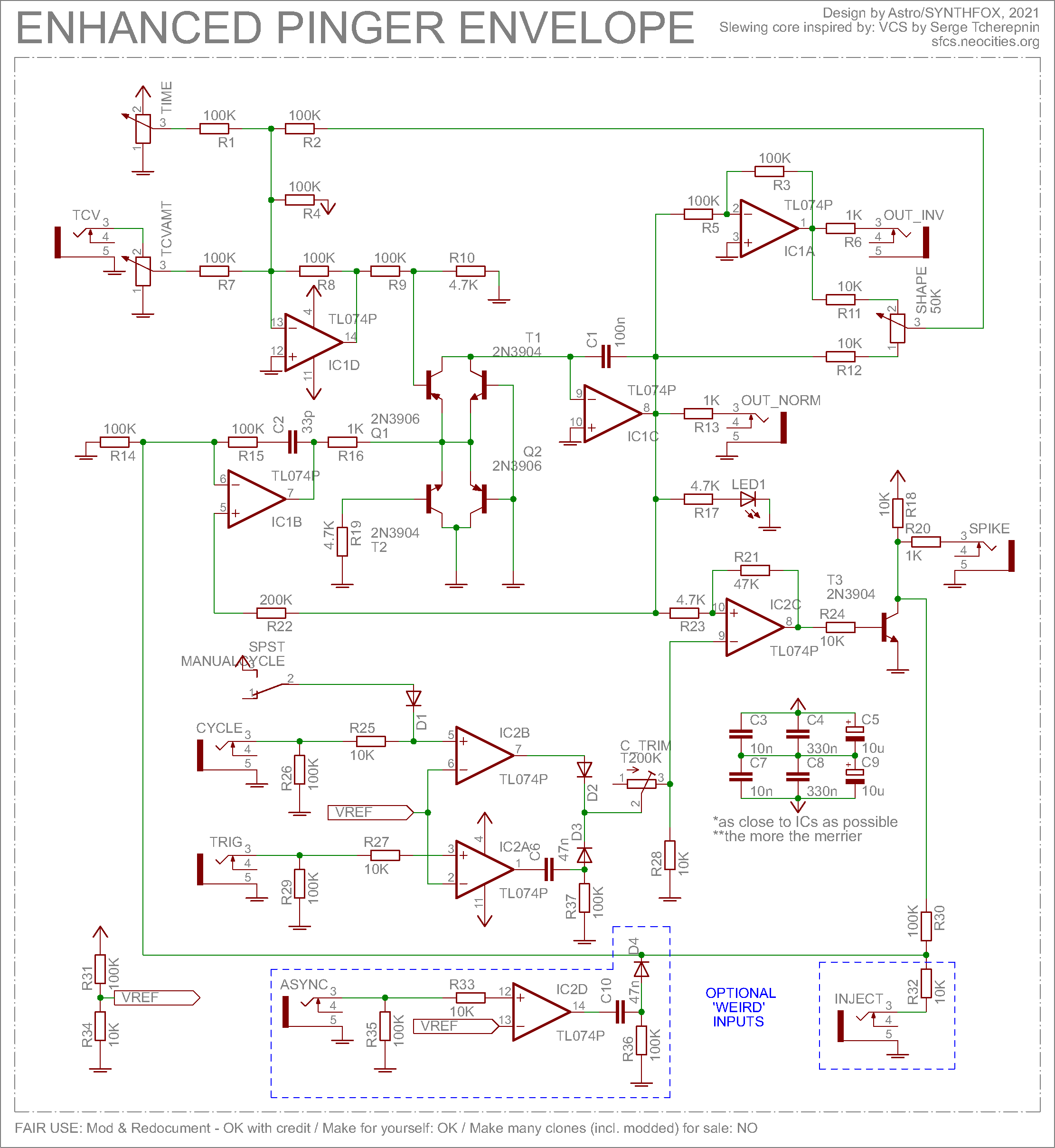
Oh, here we go again. You may want to read about my Dual Lag Processor first if you want more on point understanding of things, because the core part of the module is basically it. The Rise control was removed altogether - we want it instant, so T2 - the one responsible for rise time - has been grounded through 4.7K. The bases of the two transistors (T1, Q2) on the other side of the transistor clusterfuck - the ones you would usually do exponential control of the thole thing through - are also grounded instead of having the voltage divider: we won't be using this, too. The only transistor that gets some action is Q1, responsible for the fall time, which gets the sum of the Time knob, Time CV and Shape knob, inverted and offset up by 12 volts; that's because the fastest time is when the transistor's base is at 0v, and it gets slower the higher the voltage out there is. Essentialy, IC1B/C/D is a negative voltage controlled slew - negative as in only applies the slew effect on downwards change of the input voltage, but rises instantly.
IC1A is a usual voltage inverter that outputs an inverted copy of the IC1C integrator output. The two are then crossfaded with the Shape pot to fade between slowing down or speeding up on envelope peak, thus forming more logarithmic or exponential curves.
Next, the negative slew output is fed to a simplified Lag Processor's cycle comparator circuit, but with some other crazy footwork going on. It's easier to explain it from the other side: T3 is a simple inverter: base is the input, and the collector-R18-R20 joint is the output. Its output goes to the voltage controlled negative slew input. This inverter is driven by IC2C, a hysteresis-enabled comparator. With no triggers, its - input is grounded through a 10K resistor. suppose the comparator's output is high: this means it shifts its + terminal up a little bit throguh R21 and locks it in place. The slew limiter output would have to go negative to flip the comparator, which it won't do (unless a negative voltage is present at the Inject input, but we're ignoring it for now).
If we were to shortly shift the voltage at - input up just enough for it to become more than the voltage at the + input, the comparator would go low, driving the inverter high, thus instantly rising the output voltage of the slew limiter. And as it jumps up, the voltage at the comparator + input becomes higher than whatever is at the - input, turning the comparator high again, driving the inverter low and removing the voltage from the slew input. Slew takes its time to reach down to 0v, and we are back at the initial state. If we shift the voltage at the - terminal again (or even keep it shifted from the very beginning), the same sequence of events would happen all over.
Easy, huh? Well it's about to become even easier with all the different inputs I made.
Let's start with the cycle input/switch. We have IC2B as a comparator, firing a bit less than +12v if whatever voltage on its + input is higher than Vref (set to about 1.1v with the R31/R34 divider) and a bit more than -12v otherwise. The Cycle input is connected to IC2B + input via 10K (just to be safe). 100K before the 10K is to pull the whole construction down to ground when nothing is patched into this input. Also, a switch connects +12v manually through a diode to the + input, overriding any signal from the Cycle input. The comparator output is diode OR'ed with another comparator's output (ignore it for now), and is fed to IC2C inverting (-) input throguh a trimmer - which is exacly the place we have to "lift" in order to trigger the envelope. By having more than Vref at the Cycle input or making the switch, we permanently lift IC2C input up to where the function gets triggered, and it starts cycling, until we break the switch/have less than Vref at the Cycle input jack.
Down below is a similar composition around IC2A: it, too, is a comparator for the Trig input. If we want to trigger the function just once, we have to lift the IC2C inverting input for a teeny period of time, so this comparator's output goes through a capacitor, and a resistor to ground (it discharges the cap after the trigger has been triggered). It is diode-OR'd with the Cycle input/switch comparator out, essentially picking the maximal of the two - from which it's obvious that the cycle input will override the trigger input.
And that's not all! Why stop there when we have a vast entire spare op-amp on our IC2 TL074, IC2D? I decided to spend it on an asynchronous input circuit. We do the same thing as with the trigger input, but instead of using the short spike generated by this subcircuit to lift the inverting input of IC2C and allow the envelope to do a cycle, we inject it through a diode directly into the slew. This way, we don't have to wait for the envelope to finish its decay before firing another one, like with the Trig input. However, one could build an attenuverter for Time CV out of it, too - explore and be creative!
Finally, the Inject input also goes directly to the negative slew through a resistor times lower than the other ones contributing to the input mix, thus easily overriding the rest of the signals. This and the asynchronous trigger input are optional mods, but hey, why not to have them if you can?
Outputs of the module are obvious: the inverting and non-inverting envelope outputs (we did inversion for the shape pot, so why not to break it out?) and the envelope start spike - a very short pulse generated when a Trig/Cycle is successful. Does NOT fire on Async triggering.
CALIBRATION: the 200K trimmer is tricky to set up. Too low and it won't cycle, too much and it will cause a rare, but very irritating "runt envelope" when cycle switch/input is engaged. I first calibrated it to not cycle with Time at middle settin and Cycle switch engaged. Then i dropped Time to full CCW and slowly turned the trimmer back just to where it starts cycling. I did this a good few times before getting steady cycles (but also maybe washing the flux off the board helped with that).
Resistor note: no idea why, but the fall-related transistor of the VCS core can accept way wider range of voltages than the Rise one. I had to increase the CV sum to transistor base resistors to 200K everywhere on the VC lags for uniformity, but generally could've left the Fall ones be. Here, R9/R10 = 100K/4.7K, and it works like a charm for fall, but, somehow, not for rise.
Media
Speed range demo with the shape pot at noon (linear). Expo falls are faster, whereas log falls are slower.
Exponential and logarithmic (and inbetween) shape demo. The shape pot affects the speed considerably, so i'm playing with both of them at the same time.
Trig VS Async inputs. Trig input won't work until the envelope has reached the bottom, but Async fires it without waiting. This way, patterns ruled by subdivisions of the clocking signal are created with the Trig input, and patterns with overlapping envelopes happen using the Async input.
Putting a triangle-ish wave and then a sawtooth into the Inject input to use the module as a weird dynamics/harmonics processor. Engaging cycle brings some fake "resonance" to the "filter", and bringing shape to logarithmic makes it do suboctaves sometimes.
Full krell patch using this module and the shift core generator random values as the logic heart of the patch.
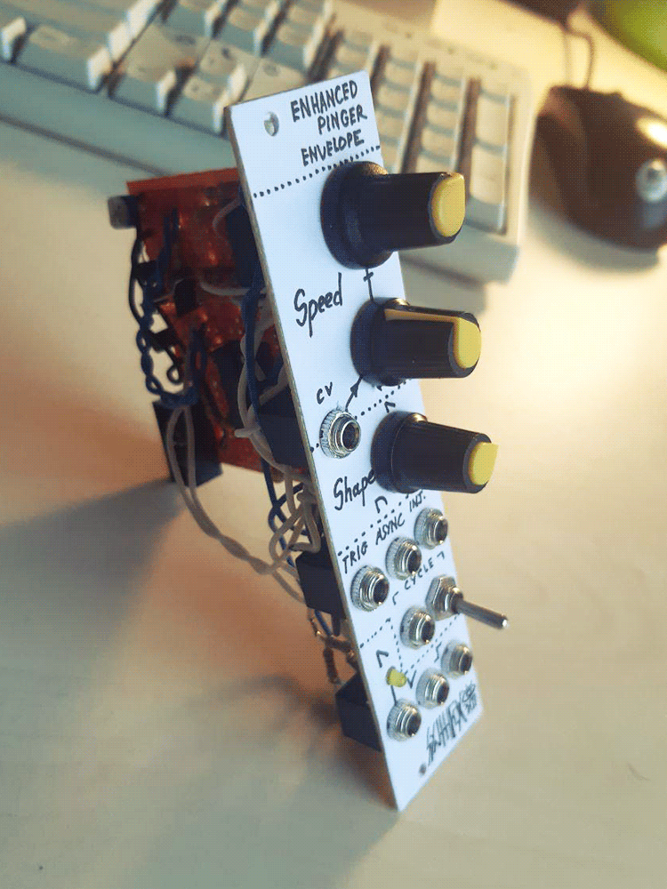
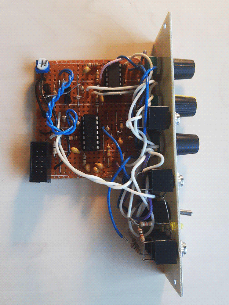
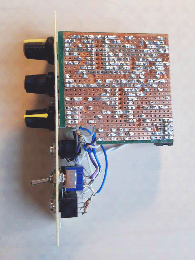
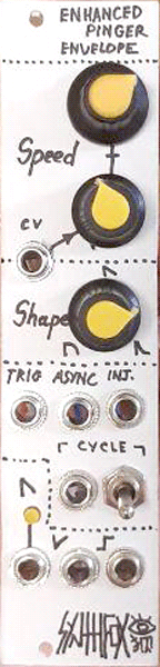
Pictures