About
This is what it says on the lid: a thing that generates slopes. Probably not all slopes in the world, but the ones we all know and love - sustained attack-release slope retriggerable on release phase, non-retriggerable attack-decay slope and a cyclic rise-fall slope. Like the Enhanced Pinger Envelope, this envelope is a specialized case of the Dual VC Lag Processor, which, in its turn, is a terribly simplified working core of the Serge VCS by Serge Tcherepnin. This module, like the other two VCS core based designs of mine, is very versatile, although, i would say, it's the least versatile of the three. Yet it implements some features that just aren't there in the other two designs.
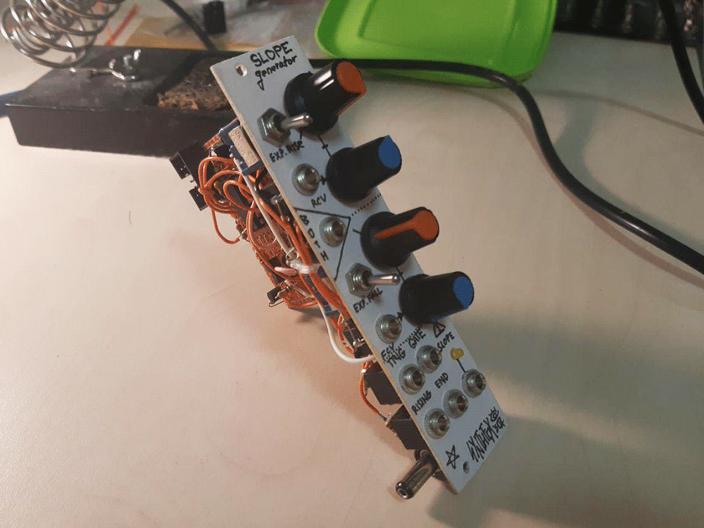
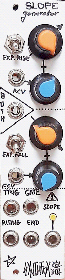
On top, there are separate rise and fall controls with dedicated attenuated CV inputs. In addition to that, both rise and fall have a dedicated switch that turns on exponential response feedback loop for rise and/or fall. This makes the slope rise faster as it reaches the peak, or fall slower as it reaches the base, producing non-linear curves, which sound more natural and sharp. With these options turned off, rise and/or fall phase will be linear. There's also an unattenuated both cv input that will offset the time base of the whole slope. At lowest rise/fall settings, putting a considerable negative voltage (about -11v) will stop the slope from moving and slowly return it to base.
The trigger and gate inputs are similar, yet have a very important difference. Each input expects a signal (> appr. 3.3v for trigger and > appr. 6v for gate) and they both will make the slope start rising. However, as the slope reaches its peak, if the gate input is held high, the slope will stay at the top until the gate input is low again. It then enters the fall phase, when it can be retriggered again through the gate input.
Usually, when we talk about gate vs trigger, gate is a long held logic high signal and trigger is a tiny logic high pulse. But in this module's terminology, this is more of an "effect" label - the trig input will gladly process the same exact signals as the gate one, and will also fire the slope up. However, when started via the trig input, the slope will fall immediately after it reaches the peak even if the trig input is held high, and won't be triggerable until it reaches the base again. This allows for creative divisions of clock signals, and so on. If fired with the trig input, the slope can still be retriggered on fall phase through the gate input.
The module has three outputs. The main one, with an LED, is the slope output: from 0 to about 10 volts. Two auxillary logic outputs, rising and end, output a logic high (a bit less than 12v) when the slope is rising/held at the top and when it reaches or rests at the base respectively, useful for programming timing events on other modules. The end output can be patched to either of the start inputs - trig or gate, doesn't matter - and the module will cycle like an LFO.
Schematic
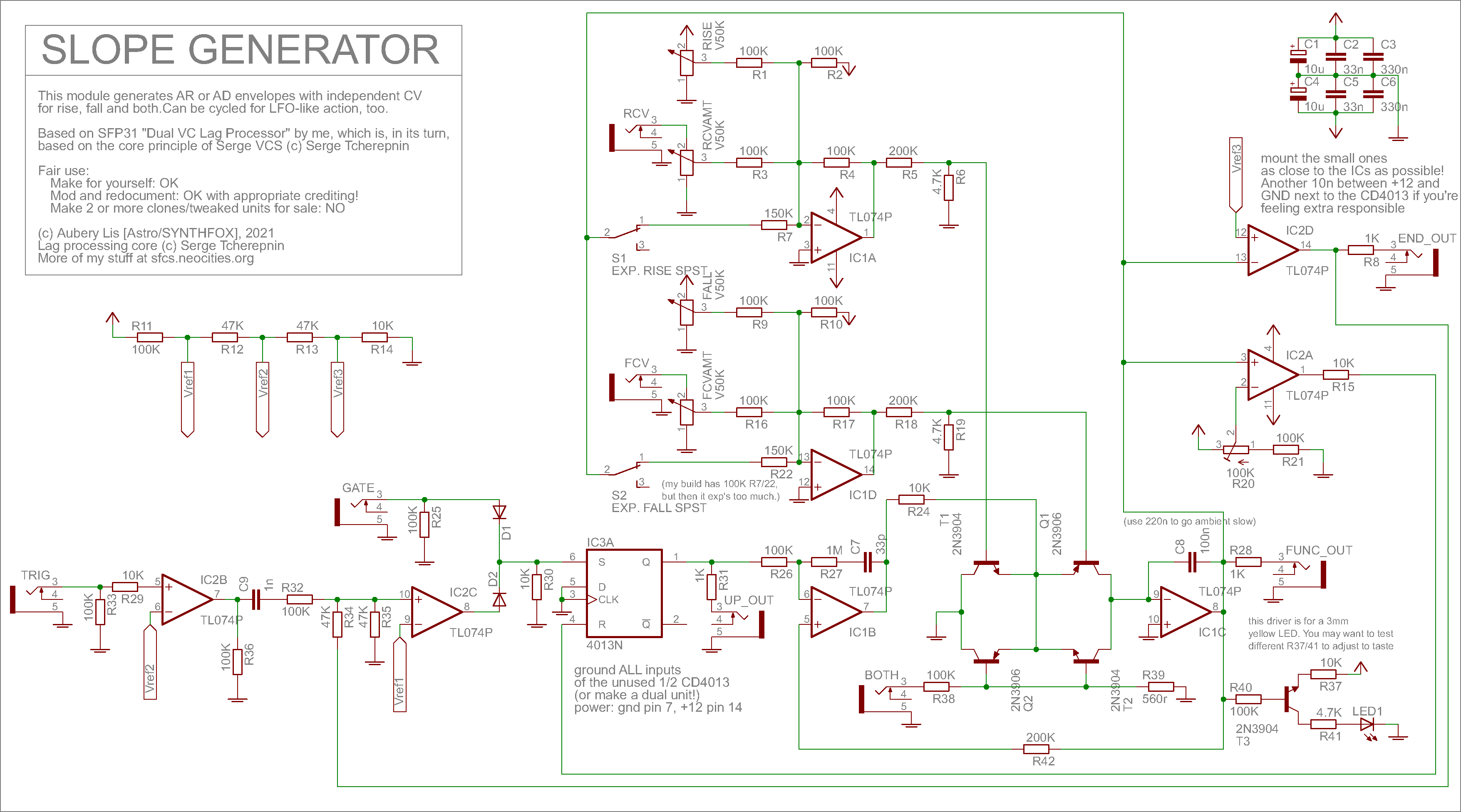
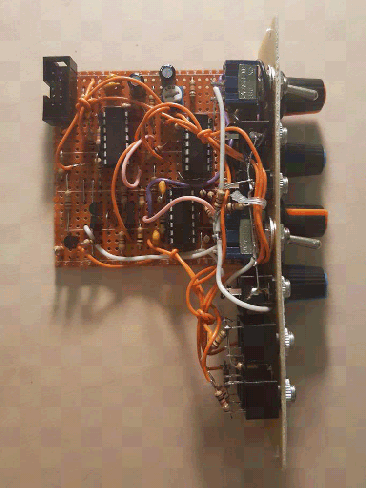
The core of the module is a copypaste from the Dual VC Lag Processor - quite literally one of the lag processors. Read about it if you want a better understanding of this circuit. The values are a bit different - the integrator capacitor is bigger for more envelopey time range, the both cv input is divided down more at Q2/T2 bases for tamer effect and almost full absence of the negative voltage + lowest time instant fall bug (still looking into it). The R27/C7 are whichever i had on hand and don't seem to cause a big difference, everything works just fine - yet i have a feeling they may be related to the fall bug, too. The slew output (IC1C op-amp out) goes to rise and fall expo switches, which are then fed back to respective CV summators. This simple feedback loop accelerates the slope as it reaches the peak and/or decelrates it while it reaches the base. My build uses 100K resistors for R7 and R22, but the effect is too evident, so i propose using 150K or even 200K for a more gentle effect.
For the logic part, we will treat everything from R26 left terminal till IC1C output as a 'black box' voltage controlled lag processor (or slew limiter): we don't care what's going on in it, but it applies some upwards lag and some downwards lag. Feeding the slew is a CD4013 - probably my favourite CD4000s IC ever - wired up as an S-R latch: its output will turn high when SET sees a logic high level (appears to be about 5.5v running off 12v), and low when the RESET sees one. Important to note is that if both SET and RESET have logic 1s on them, both Q (output) and !Q (inverse output) will stay high, which, since we don't care about !Q, means SET takes priority in our case. The rising output is directly taken from the latch's Q output, and it shows when the output of the slew is either rising or resting flat at peak. By the way, CD4013 has TWO such latches, so it definitely calls for a dual slope generator module; i just don't have rack space and ran out of parts.
Imagine the latch has 0 in it to begin with, so Q is 0, slew output is 0v. If we were to put sufficient voltage into the gate input jack, we would write a 1 into the latch, setting Q to logic high (about 10 volts). The output of the lag processor will soon catch up to that voltage and stay flat on it. But now we need a mean to reset the latch and enter the falling phase of the slope. This is done by IC2A - a comparator that fires almost 12v if the slope reached its peak and almost -12v otherwise. Its output is hard-wired to the latch's RESET input through a 10K resistor (negative voltage protection), so whenever the lag processor's output hits the peak value, the latch resets and the lagged output starts falling down to zero. However, with the gate input wired directly to the SET input of the latch, as long as we have a logic high on it, the latch output will stay high, and will only get reset by IC2A when we no longer hold SET high. This is how the gate input provides a sustained envelope option.
A more interesting, slightly brainfreaky part is the trig input. It would seem that to make the envelope go up and down immediately, we would have to just input a very short gate (or, a trigger) to the gate input and call that a day. Not so fast: this way, we still can retrigger the slope on its way down. Imagine a constant slow narrow pulse running into the gate input - it would basically lock the slope output to oscillate near its top values in most cases. For this reason, the IC2B/C/D WTF exists.
It's easier to unwind this from the end, as always: IC2D is a very simple comparator that compares the slope output to about half a volt and outputs about +12v if it's below this half a volt, or about -12v otherwise. I called it an end comparator, as it usually would fire upon slope's return to base, and it drives the end output jack. Also, it goes back to IC2C's non-inverting (+) input through a 47K resistor, and then through another 47K to ground, so we get about +5.8v or -5.8v at IC2C +, depending on the end comparator's state. This IC2C is also a comparator - it compares whatever is going on on its + input to the 6.1v on its inverting input (-), and its output drives the latch much like the gate input.
But wait, +5.8 and -5.8v are never more than 6.1v in order to fire the slope! Yes, this is when the capacitor and resistor in series (C9->R32) come in play. They are driven by another comparator behind it, which shapes a pulse out of some signal on the TRIG input by comparing it to about 3.3v. This pulse goes through a capacitor and produces a short positive spike when flipping up, or a same negative spike when flipping down. These short spikes are added to the +5.8v from the end comparator, which would normally be there if the slope is in rest (=> at base => end comparator is high). We can ignore the negative spike - it serves no use for us, but the positive spike (which happens when the TRIG input signal crosses 3.3v upwards) drags the + node just above 6.1v to fire the slope. The end comparator then turns low and drags the IC2C's + down to -5.8v: no matter how many spikes we fire from IC2B now, they won't cross 6.1v and retrigger the slope until it reaches the base and turns on the end comparator again. The short pulse generated by IC2C is diode OR wired with the direct gate input, so even when launched thorugh trigger input, the slope can still be retriggered on its fall phase via the gate input.
CALIBRATION: set the trimmer so that it is shorted to +12v. Set rise to noon, fall full CW. Trigger the slope - you will see the LED rise, but not fall, because the voltage at IC1A - is almost 12v, and the maximum slew limiter output is lower. Slowly turn the trimpot back until the LED blacks out. Trim it just a teeny bit further than that for stability reasons. You're done. Also. Approximately: Vref1=6.1v, Vref2=3.3v, Vref3=0.6v. This can be done differently than i did it, but i did it the most resistor number effective way. Can be done by running a "resistor thread" around a TL074 from its + to some ground trace nearby. These voltages are important for envelope's logic: don't mess with them if you don't know what you're doing. Also[2]: connecting an LED directly to the slew out instead of using a driver caused me some issues. LEDs are power hungry, so multing the slope out to more than 3 destinations when the LED has no driver made the slope lock up at the peak. Some different resistor values may be suitable for your LEDs: pick to taste.
Media
Default time range. Slope cycled by patching end to trig for simplicity, both rise and fall set to linear (expo range will be quicker).
Trying out different combinations of expo switches. The effect is very powerful, that's why i decided to cut it down a little for the proposed schematic. The slope controls both the VCO pitch and the VCA volume.
Difference of trigger vs gate. An envelope with tiny attack and moderate decay is first triggered with the sequence driving clock, then gated. Trigger results in subdivisions, gate results in overlapping, similarly to the pinger trig/async inputs.
Pictures