About
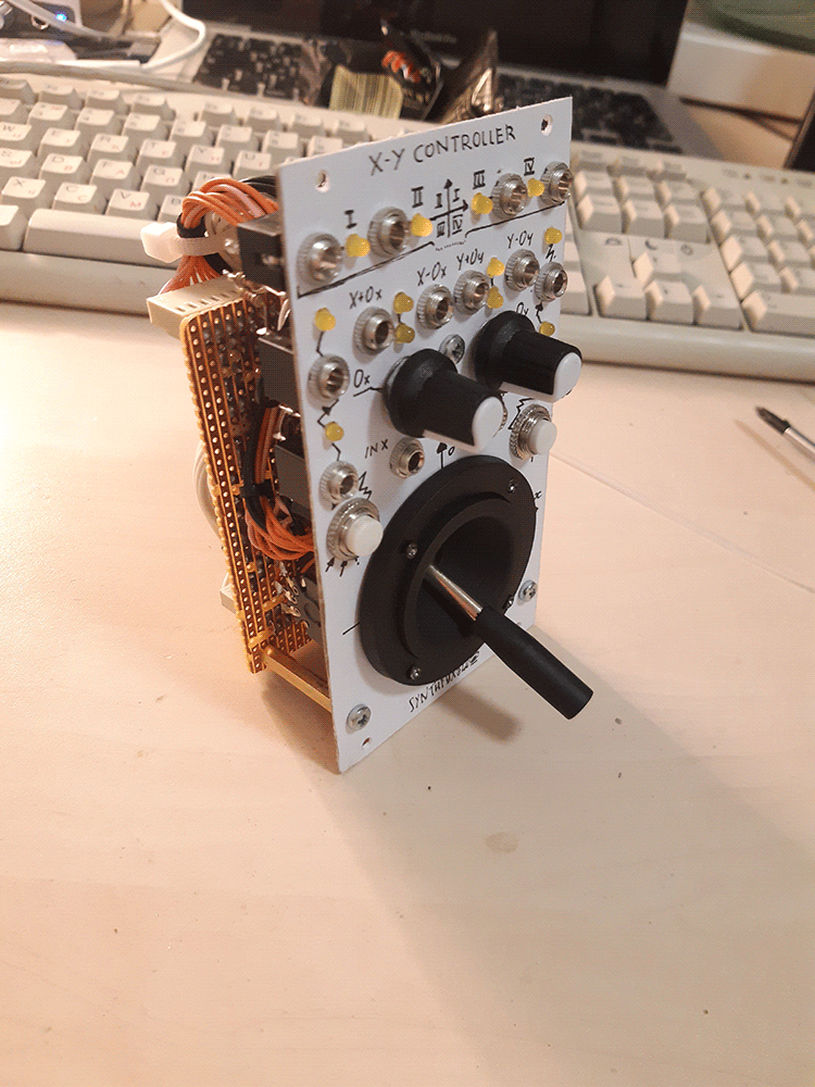
I had an analog 2-axis joystick laying around since i was 18 and sure i can build a good analog joystick controller. Now i'm a bit older and i finally did, so may i present - the X-Y controller! Basically, a slightly overfeatured analog joystick module that can be patched to control anything. By moving the joystick, you can smoothly move between the maximum value for X and its inverse horizontally, and between the maximum Y value and its inverse vertically.
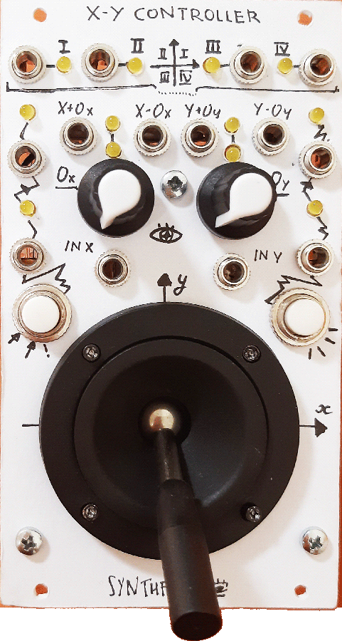
It has a joystick (naturally..) and two push buttons as the control interface. Each button outputs a pulse on push, and also has a 'toggle' output which toggles logic 0 and 1 on push. The joystick's X and Y axis are processed the same way each - there's an offset knob, and a dual output (+offset and -offset) for both X and Y.
Additionally, there's X and Y inputs (+12 normalized to both) - these determine the current maximum voltage for the axis, and then the joystick fades between it and its inverse, with zero in the center. This way, the joystick can be, say, a VC polarizer, or even a sound processor.
Finally, the module has a quadrant detector on the very top. It processes the pre offset X and Y values and determines, which quadrant of the Decarte coordinate system the resulting point would fall in. This can be used in conjunction with an AND module, such as 2x3AND, to allow certain events only if the joystick is in a particular position.
Schematic
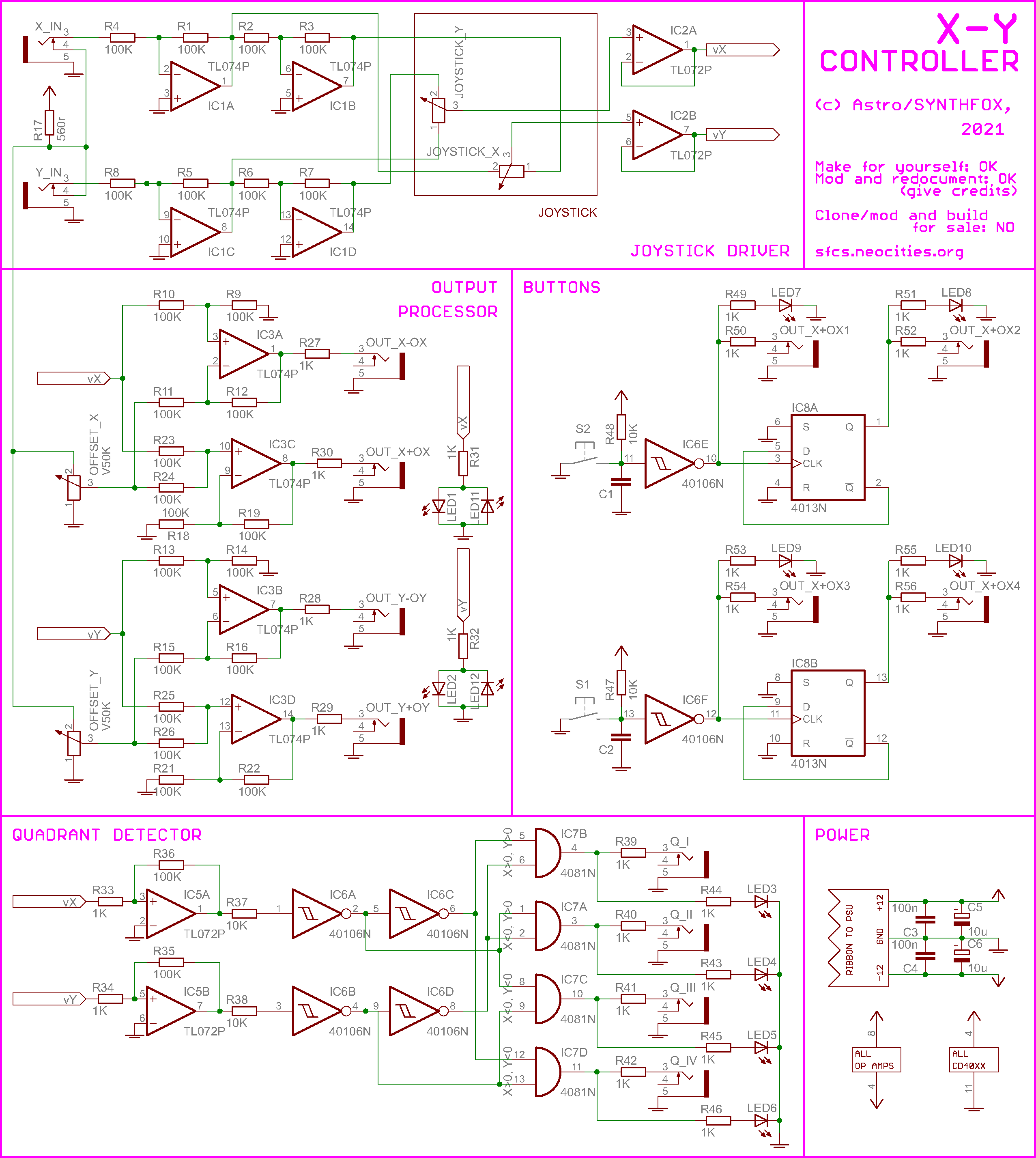
This module is very simple, and relies on basic op-amp operations. The joystick is, in essence, two potentiometers - one for X and other for Y. It just so happens that they're mechanically tied to a handle! I exploit this by using them as a usual "dry/wet" knob, but instead of dry and wet, i use and inverted and a non-inverted (double inverted, in fact) copy of X_IN (or Y_IN for the Y axis). +12V is normalised into both input sockets, so if nothing is plugged, we get +12 as the maximum and -12 as the minimum for both axes. IC1 does the inverting job, and IC2 buffers the axis output for further processing.
The post-buffer outputs are processed by some op-amps (IC3) - one simple adder and one simple summator per axis, adding and subtracting the offset set with the knob and outputting the offset voltages. Of course, if offset is set to full CCW, the two outputs will be (very close to) identical.
Also, the pre-processor output of X and Y axis are compared with 0 by IC5. Mind the feedback resistors for hysteresis - otherwise the quadrant detector will be buggy around the center! We have to compare the axes' outputs to 0, and then make CMOS-friendly inverted and non-inverted copy of the comparators' outputs, in order to detect quadrants. The four quadrants are: x>0 & y>0 (I), x<0 & y>0 (II), x<0 & y<0 (III), x>0 & y<0 (IV). We can rewrite x<0 as !x>0 (! is inversion, logic 'not') - and same for Y. We're getting both these events with the 40106. The "&" part is carried out by the 4081 AND logic. One of the 4 outputs will be lit up at a time, pointing at which quadrant the joystick is in.
Last not least, there's the 2 buttons. They are pulled-up through resistors and debounced using the 2 remaining 40106 NOT gates and capacitors. The post-40106 output is the push event. It's then fed to a 4013 set up as a simple frequency halver - every time it receives a pulse at the clock input, it toggles its output to the opposite (0 to 1, and 1 to 0) - hence the toggle action.
Media
offset set to 0, X and Y axes controlling frequencies of the two halves of the 40106 VCO in independent mode. Two triangle outputs mixed and recorded.
Same as above, but left dual VCO half is removed from the mix and FMs the right half. Crazy stuff!
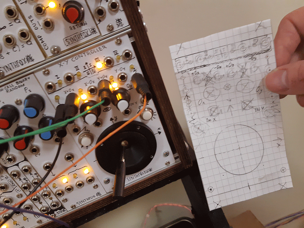
A sketch demonstrating more uses for the joystick: X axis controls the sequencer speed, Y+offset controls suboctaver gate opening, Y-offset patched to suboctaver/original triangle crossfade. The offset feature really helps balancing the fades out.
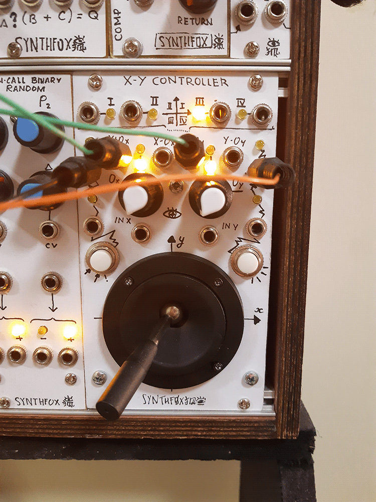
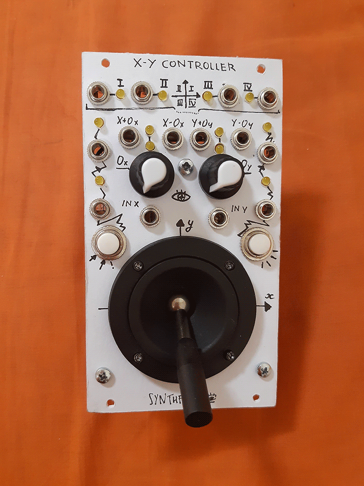
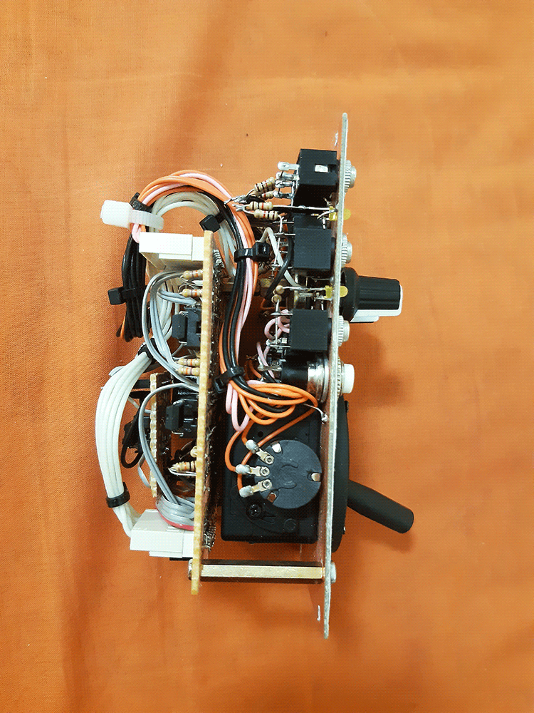
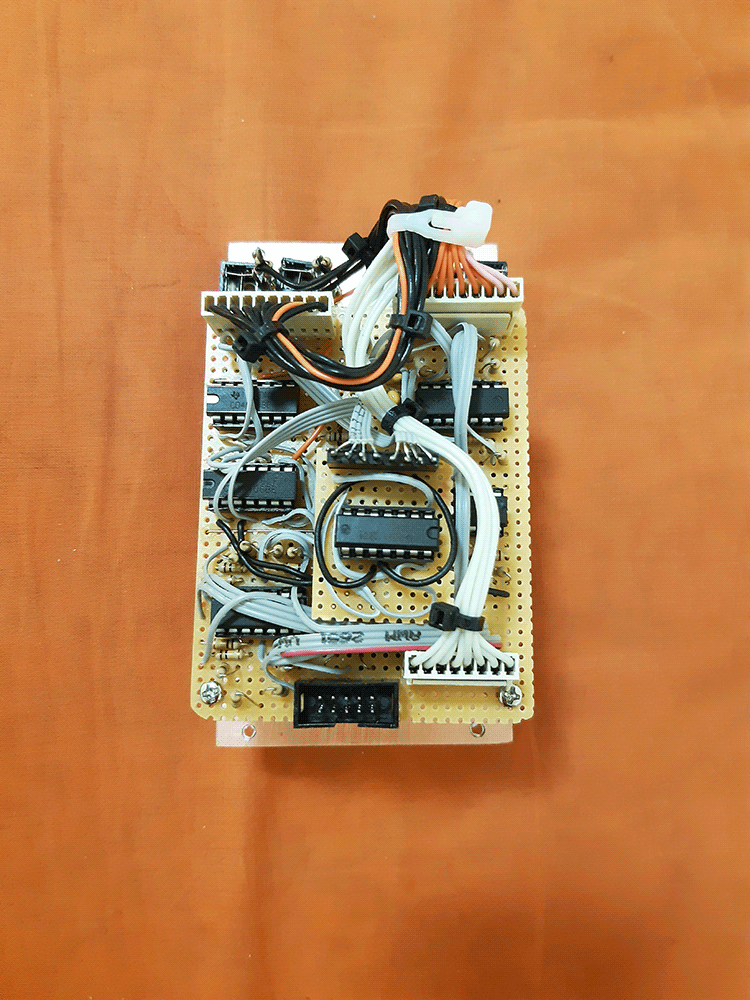
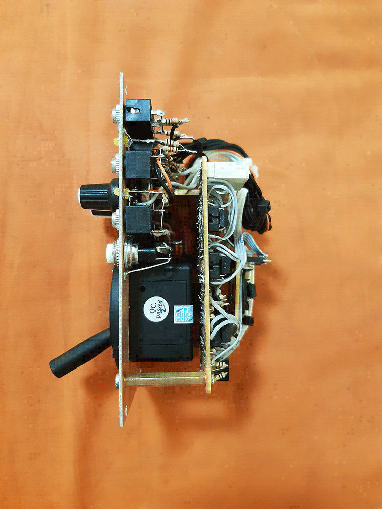
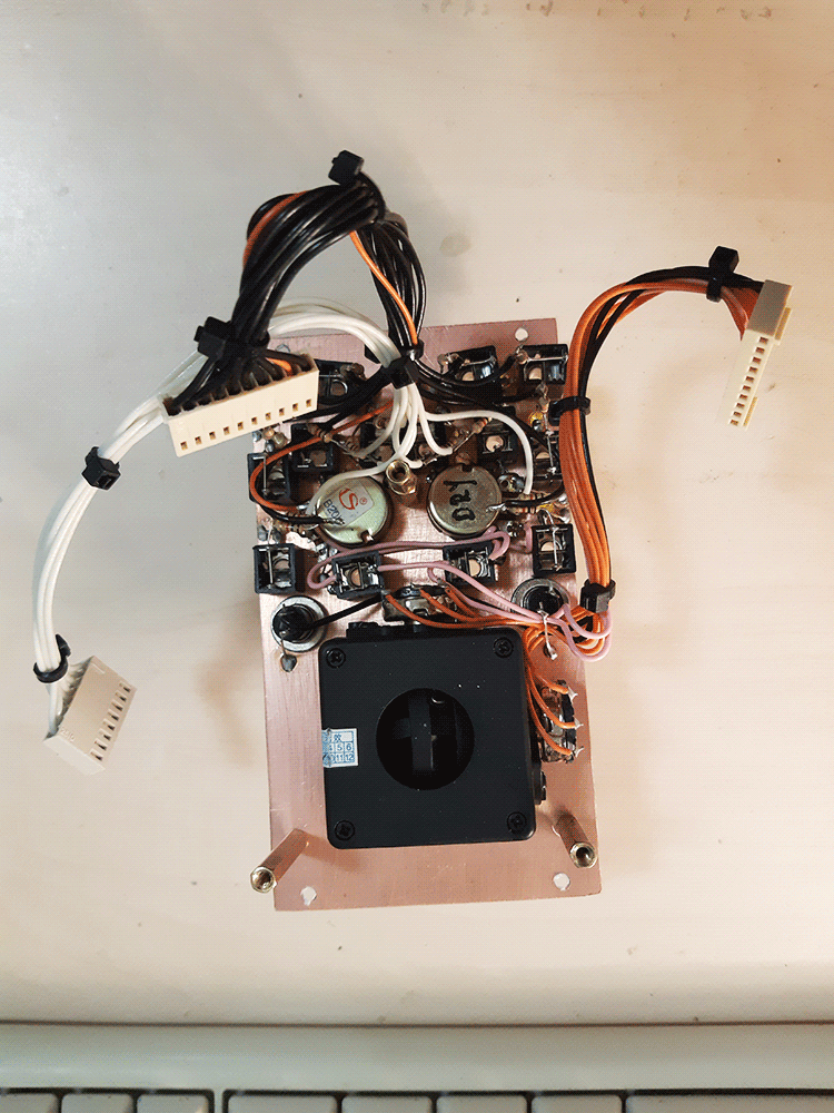
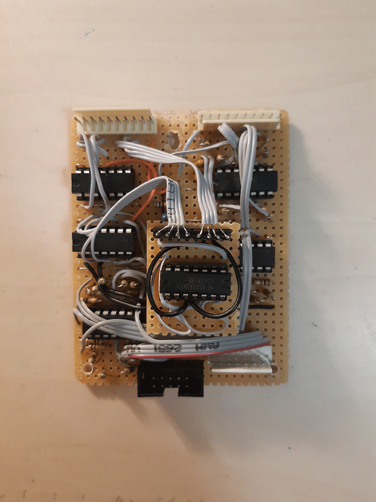
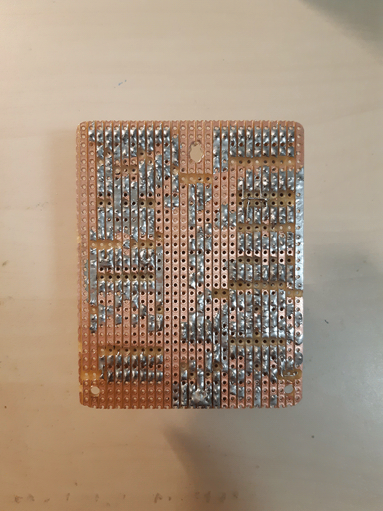
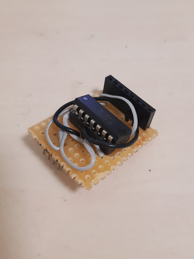
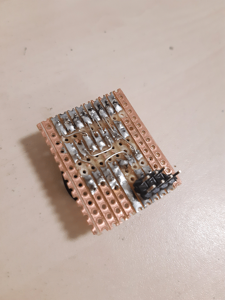
Pictures