About

2x3AND is a slightly weird take on logic gates. I had a vision before i went to sleep the other day: i need to make a dual 3-input AND logic for my synth, and it has to have a common threshold control with CV so it would be able to process CVs as well. So i was like, alright brain, i have that 4 HP blank somewhere under my bed, maybe it's about the time i did something useful with it. So i did.
NB! THIS DESIGN SEEMS SKETCHY! I have no idea why, but the op amps heat up a little bit when operating. It seems that ORing them with diodes like this isn't much of a great idea. That said, it worked just fine for about 7 hours and didn't overheat at all - just a slightly notable heatup, so i may consider it safe. It MUST mean it draws more current than it could, though. So please, if you're an actual EE specialist, unlike me, take a look and tell what am i doing wrong. Thanks!
So, anyways, what this thing does is the AND operation over 3 inputs. The output is a logic signal, that goes high if all 3 inputs have voltage above the threshold at the same time. The threshold at which the input is treated as logic 1 is controlled by a threshold knob and an external TCV input, and it's common for all 6 inputs. The first input of each 3AND gate is pulled down with a big resistor, but the other two have +12V normaled into them, so it can act as a dual comparator with common threshold control. Likewise, you can use just two inputs and use it as a usual AND gate, or use all three inputs.
This module is aimed for working with logic signals (creating "unlikely" events or complicated rhythmic patterns), but also is capable of processing CVs and sounds - it starts generating wild gates if it processes CVs and has its threshold modulated by another CV.
Schematic
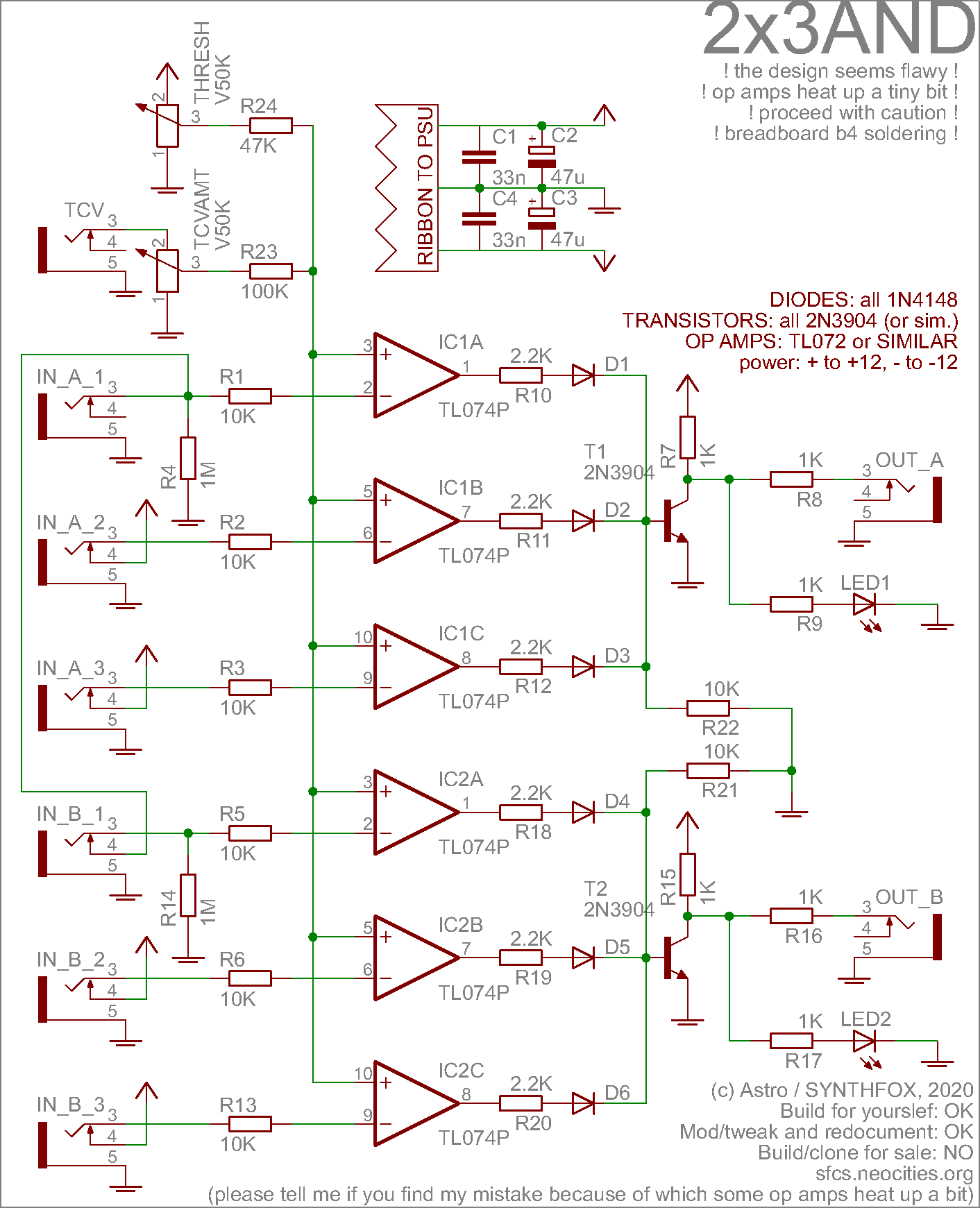
At first, i thought of getting a dedicated CD40XX chip, making nice usual comparators for the inputs, and doing everything neat and great. But then, i remembered that 1. i'm punk, 2. i don't have a lot of money and 3. i will be waiting for the said chip for ages here in Tallinn. So i decided to go the crudest way possible.
If you think of it, a classic 2-input AND gate is basically an OR one with inverted inputs and inverted output. Something like "not ( notA or notB )", or, in human readable, the output does NOT go high when either one OR the other input is NOT high. Even more human readable: the output goes high when both inputs are high. This is for the classic two input AND gate, but it's the same deal for three inputs.
Apparently, this setup is implementable with a tiny part count! Since i want input to be CV-friendly and with presettable threshold, it means i want an op-amp as a comparator at each input. After it, i would need to invert the result, but obviously i can just swap the + and - inputs places and get a comparator with an inverted output: now it tells when the incoming signal is less than the threshold value, not more.
After that, i OR the three logic signals coming from op-amps with a simple diode OR gate: nothing special, just 3 diodes. The resistors after the op amp outputs prevent the direct connection of 2 outputs to each other when they're high (or something) - without them, the op amps overheat. With 1K they heat a tiniest bit. So i put 2.2K on the schematic: i with them, it's going to be OK, i think. This is the sketchy part about this design.
Finally, i invert the result of the 3-OR gate with a simple NPN transistor inverter. Plain and simple. Output is current divided between an LED and the outptut jack.
Worth noting how out of the 3 inputs, 1 is pulled down with a 1M resistor, and the other two are normalized to +12v directly: if you decide to remove the normalling, or are working with a banana system, better pull them down as well!
Media
3 clock signals fed to one AND gate: a slow one, a faster one, and a fairly fast one. They create this repeating gated woodpeckerish trigger pattern, that triggers an FM drum.
Same patch, but instead of clocks are some CVs (an LFO, a pseudorandom fluctuating voltage and a random quantized voltage). The threshold is modulated by another LFO. This makes up a more complicated and unpredictable pattern that has its unique motives and features.
Just a little showcase of PWMping a sawtooth from my oscillator - modulating the pulsewidth by hand and with an LFO.
All triggers in this demopatch are derived from the module. With careful selection of inputs, extremely interesting musical motives may happen: i like this one a lot.
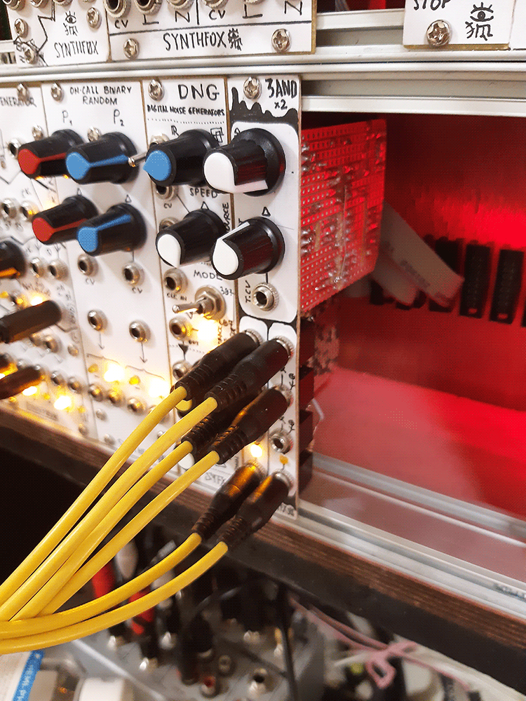
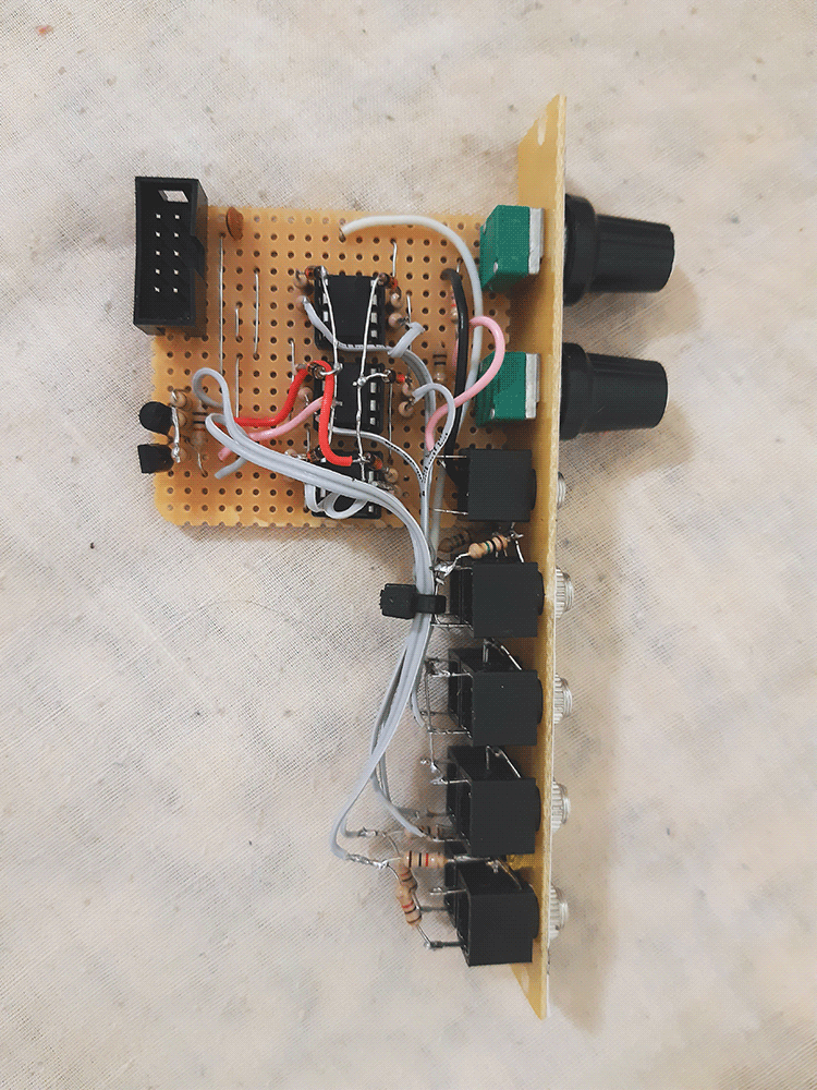
Pictures