About
I really wanted an oscillator with a huge frequency knob, so i designed this.
WARNING: this VCO is 1. imperfect, 2. not super easy to build. If you don't feel like an 'intermediate' SDIYer, start with an easier project!
UPD 15 MAY 2022: i have made a way more part-efficient, better-tracking and simpler to build new VCO design using the same exact principle. And built three. In a proprietary, banana jack enabled format, => also looks better. Check it out, too!
UPD 08 AUG 2022: i also made an OTA-based fluid shape complex VCO pair. If you're looking for something more 'serious', with better tracking and way extended modulation/shaping options, check it out. This design is still very nice while not being much trouble for an intermediate-level builder, though!
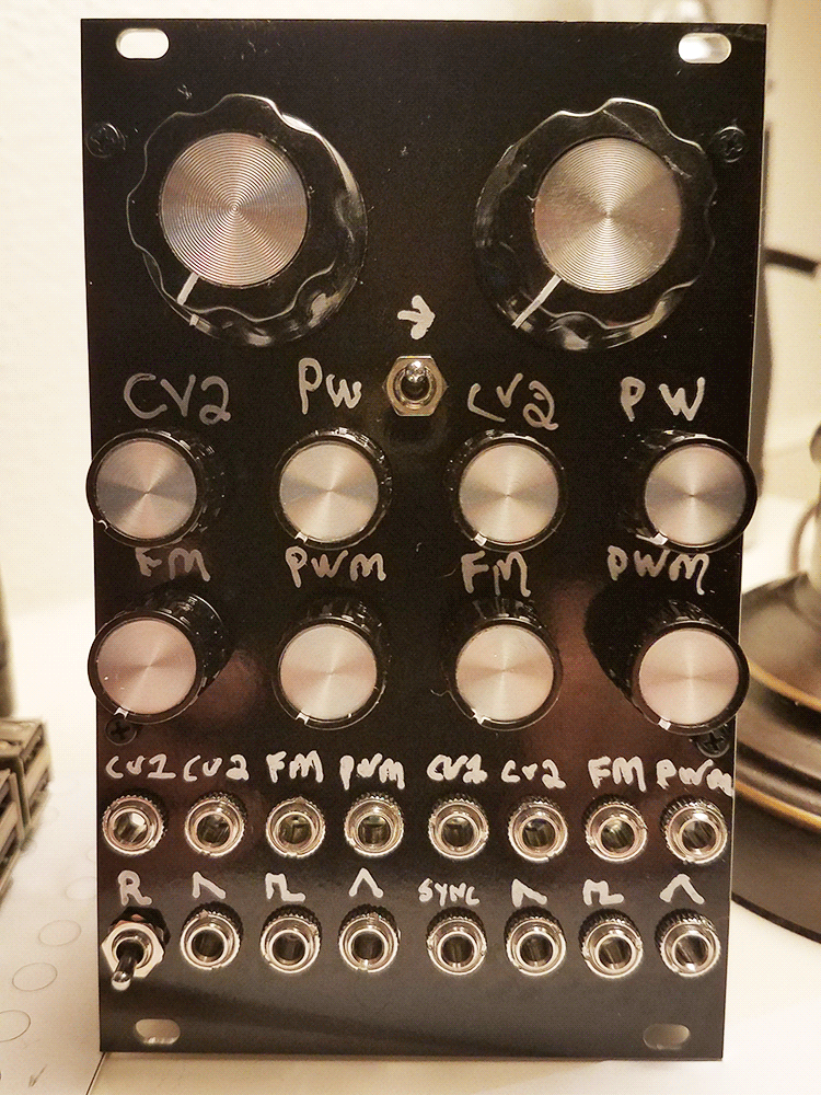
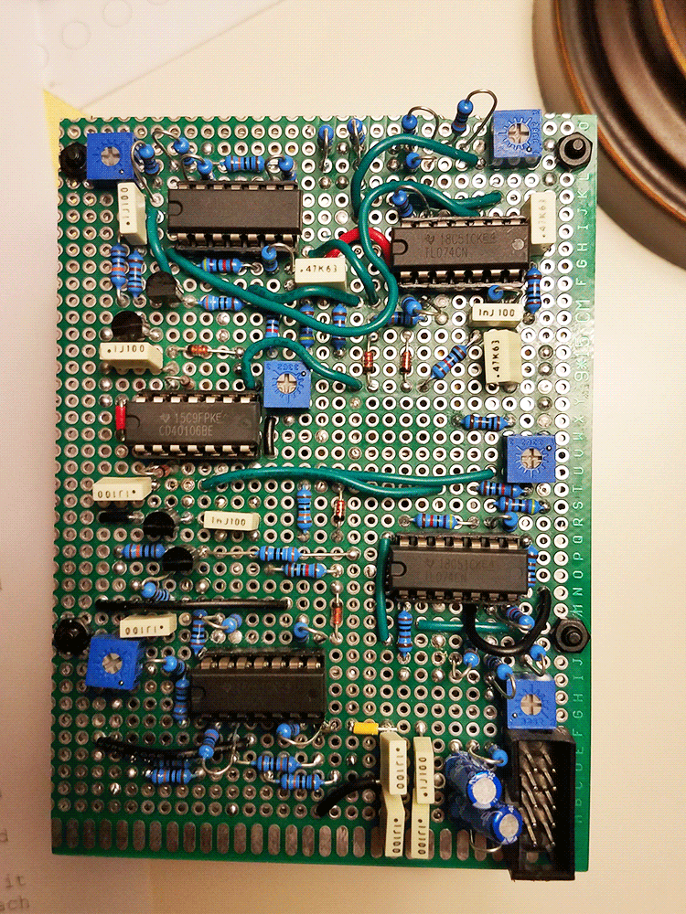
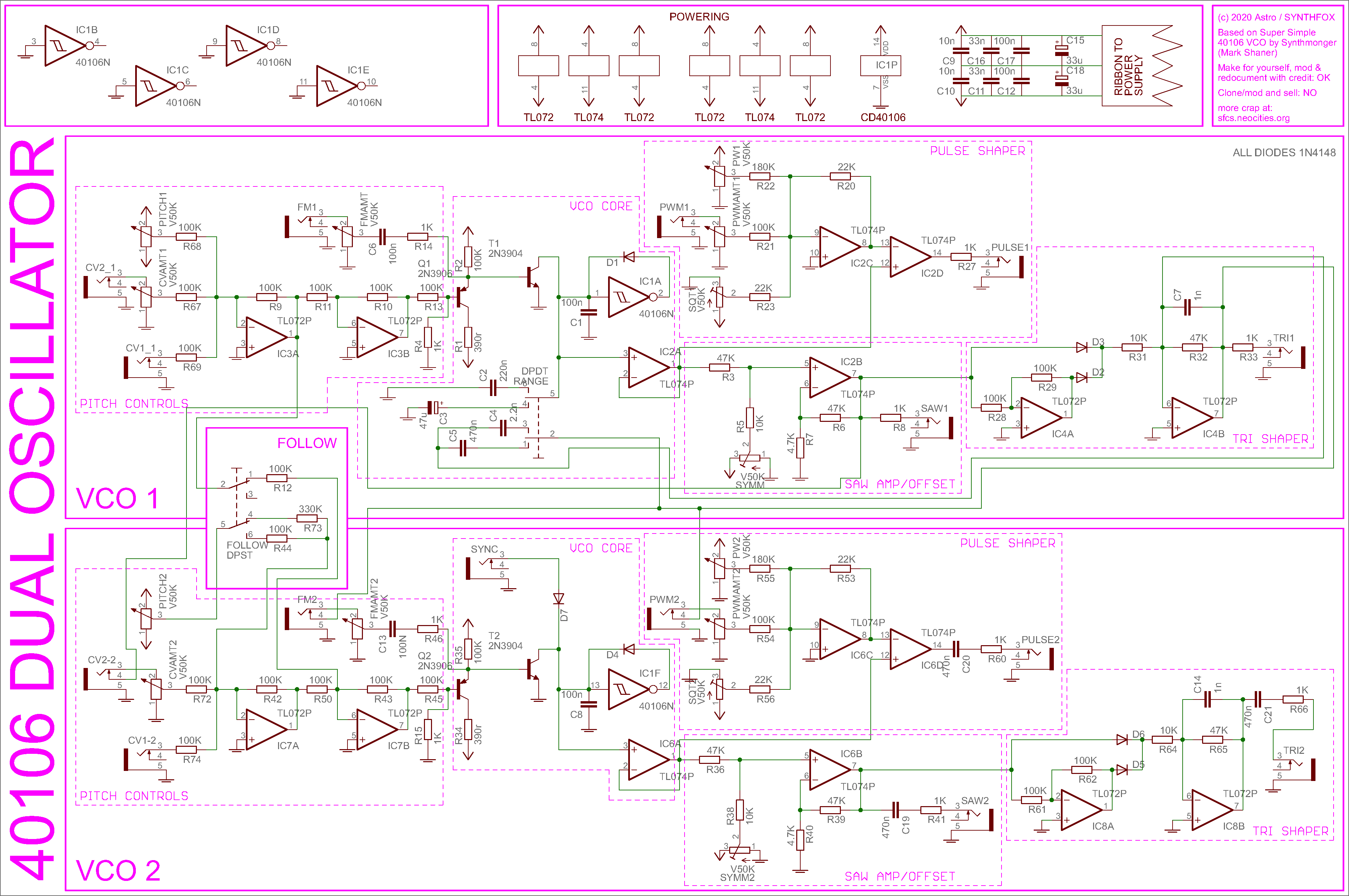
Now that i scared you all, time to talk good words: it's EXTREMELY good for a part count this low. It has exponential tracking (1 v/o possible!), linear FM and a huge frequency range. The schematic may be intimidating, but the actual oscillator core is simple and consists of one sixth of a CD40106 hex inverter, a diode, two transistors and three resistors. Everything else is additions to make this VCO usable, but you can go ahead and simplify it as much as you can. The original oscillator core was designed by Mark Shaner/synthmonger - i found it in this topic and decided to turn it into a full low-cost VCO for sytnhesizers, and i can't be more happy about how excellent it turned out. Up to 6 such VCOs can be built around one 40106 - each will require two TL074s for full operation, although synthmonger says (and i confirm) that they will bleed when maxed out, so i suggest sticking with a maximum of 3 on a single chip. My design has separate sawtooth, pulse (with PWM!) and triangle outputs. The triangle shaper is crude and simple, so it outputs a slightly buzzy triangle - you could softclip it in various ways, but i was pretty happy with the result as it is. Each of the two VCOs have two CV inputs, one with an attenuator. They also have an FM input (AC coupled). Left VCO can operate in 'bass' or LFO mode (the R switch on the left) and its outputs are DC coupled. Right VCO is always in sound mode, has a sync input and AC coupled outputs. The coolest thing about having two of these in one package is using them as one layered/FMmed voice; for this purpose, i installed a 'follow' switch (the one between the big knobs). When toggled up, it makes the second VCO 'read' both CV inputs and the pitch knob of the first VCO, and turns its own pitch setting knob into a detune knob. Separate CV of the second VCO is still available in follow mode, so you can get VC detune, for example.
To my surprise, the circuit works excellently. In follow mode, the VCOs barely detune from each other, and the module is even usable as a somewhat crude FM pair. When melodically sequenced, the melody suffers no loss when transposed around. That said, the unit is pretty damn temperature dependant - it drifts if i breathe on transistors on the board for half a minute. Heatpaste the 3904/3906 pair together for better stability! I didn't and i don't care. Also, i didn't include any v/oct or CV range trimmers because i am a punk, and they just happened to stay in tune in follow mode to my surprise - so i'm sure some trimmer shamanism would make them perfectly matched for each other for FM purposes. But this part is up to the builder.
If you tried building this before 13 Feb 2021 - lord let your soul heal. I missed out one resistor on the schematic, but included it in the build! Without it, the VCO simply has 3 frequencies - middle, ultra high and super low. I'm terribly sorry. Note R4 and R15!
Schematic
UPD 01 OCT 2022: a SDIY enthusiast basmaster003 (Brian Alan) attempted the build and contacted me on some problems. Despite most of them being bad op amps or stray shorts/cuts, we did find out that one resistor on the schematic was overlooked by me. R23 (and R56 for the other VCO) was 100K, whereas in my actual build it is 22K - now fixed on the schematic. This was due to me copying parts and forgetting to change the nominal. Having 100K in place of 22K made the trimpot not provide enough offset for the pulse output to work. I don't think anyone attempted this build so far, but if you did - sorry! Kudos to basmaster003 for finding this for me.
Click here for a version without pink block dividers and labels
this is a FAIRLY SIMPLE oscillator design, for what it offers. It is saw core - the oscillating element is the 40106 shmidt trigger, and it generates a quiet, positively offset sawtooth at the input terminal and an extremely narrow pulse at the output. If you don't know how a basic 40106 oscillator works, please, read up on it. Then there's the magnificent voltage control solution by Mark Shaner/synthmonger - the NPN transostor is what controls the pitch, and the PNP one is the current sink. The core of the VCO is THAT simple, and provides UPD May 2022 briefly on why it oscillates: assume C1 is discharged and voltage at the inverter input is 0. Then, the inverter output is logic 1 (about 12v). The schmidt trigger quickly charges C1 through the D1, until the voltage at the C1/inverter input junction hits the up-going threshold. The inverter output flips down, and C2 discharges through the PNP/NPN setup until the voltage at the 40106 inverter hits the down-going threshold. The 40106 inverter output flips up again, almost-instantly charging the capacitor to the inverter's up-going threshold, and so on. The process repeats again and again, forming a heavily offest down-going sawtooth at C1/D1/40106 inverter input junction. The NPN transistor acts as a path to discharge the capacitor, and the PNP one is an exponential current sink. Additionally to that, using a two-transistor setup like this compensates most of the thermal error, meaning you can live happily, although still imperfectly, without the tempcos. The same exact stuff goes on for the second VCO. end UPD A dual-invertion CV summator block's output goes into the PNP's base - a simple double-invert sum and buffer.excellent nice volt per octave tracking. If i am fully honest here - i don't really completely get how this transistor setup works: probably, some person with good knowledge of actual circuit analysis could add to this article
The rest of the circuit is basically waveshapers. The pulse shaper is just a comparator, and a summator for PW control and PWM input. Trim the trimmer so with no CVs and both handles fully CCW you get a 50% duty cycle pulse.
The triangle waveshaper and sawtooth amp are kinda paired together and depend on each other - the amp amplifies the sawtooth and removes the DC offset, and the triangle shaper makes an inverted copy of that sawtooth, then performs a diode OR of it and the original (whichever has higher voltage gets to the output buffer, other is ignored) - and so, a triangle-like waveform is obtained. It's far from a perfect triangle, but it's a smooth, symmetric wave. Some lowpass filtering is happening at the output amp for the triangle, as without it, it would have an annoying click. Drawback: the output gets a bit quieter at higher pitches. Listen to the triangle output and adjust the trimmer by ear, triangle gotta sound the smoothest way possible.
There are two switches on this module - a range switch for the first VCO, and a follow switch. The first one adds a capacitor in parallel with C1, so the overall capacitance increases and the pitch range drops. Either a small capacitor (bass mode) or a big one (LFO mode) gets connected. Respectively, more capacitance is added around the triangle output filter stage, because it has to do more lowpass for lower ranges, since the click will be longer in time. The follow swtich is tricky - when up, it takes the inverted sum of the first VCO control voltages, and puts it to the same inverting buffer VCO2 inverted CV sum is going to, effectively adding everything VCO1 "senses" to VCO2's pitch control. THE VCO2 pitch control knob is then ran to the summing node through a 330K resistor instead of 100K one to decrease its range to detune; with 330k it's about +-2 octaves - i left it like that for FM reasons. If you just need it to detune a few semitones, increase R73 to 1M.
The outputs of VCO2 are DC decoupled through capacitors, but VCO1 outputs are direct: that's because it can operate as an LFO, or even a clock oscillator. If you are not planning on using the LFO mod, add capacitors to the outputs, like on VCO2.
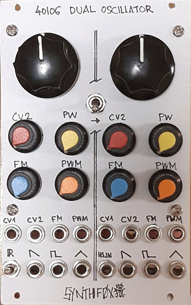
basmaster003 plus version
Once upon, one brave Brandt Alan A.K.A. basmaster003 reached out to me on topic of this module with troubleshooting questions. He ended up building one - you can see the photos down below! Then, he went as far as pushing the design as close to perfection as possible - at least in my eyes; out of the improvements are better stability and less pitch change lag thanks to the integrated transistor pair, improved tuning and knob range, consistent waveshape amplitudes, and so on and so forth. It's quite amazing - i myself moved on and figured out a different VCO core that simply is easier to make behave well, yet Brandt stuck with this halfways-hacky design and brought it to the top. Who knows, maybe further developments of this adventure are still ongoing!
Brandt generously allowed me to present his kicad files for download. Anyone with kicad can go ahead and dig around, or even make your own! As a practical side note, the SFP21 core doesn't use an OTA, unlike my latest endeavours, which ultimately puts it above my more up-to-date designs in terms of being somewhat futureproof as of part availability; OTA supply shows an ill tendency, whereas CD40XX logic stays strong, for now.
Media
Basic VCO sweeps, just with the big knob, up and down. Both VCOs have about this range, + the left one has a bass and an LFO mode with lower ranges. Saw, square and then the triangleish output. Pretty impressive.
Demo of the pulsewidth modulation. Keep in mind, that the duty cycle is 50% when the PW control is full CCW, but as you turn it/apply CV, the HIGH part of the duty cycle will increase, and the low will decrease. Easily fixable by replacing the = and + inputs of the comparing op amp.
Left VCO triangle is normalized into right VCO's FM input. I play around with it a bit, listening to the triangle output of the right VCO.
Left half can become an LFO by flicking a range switch. Here, i play around with the right VCO sawtooth normalized into right VCO's CV 2 input - quick and loud dub siren rave lazor!
Showing off the follow feature and exponential tracking here - the pair stays pretty much tuned despite me transposing the right VCO around, and both by turning the left VCO's pitch control.
A little demo patch: the module operates as an FM pair, right triangle output goes through a passive LPG and some envelope/sequencer logic runs all of that.
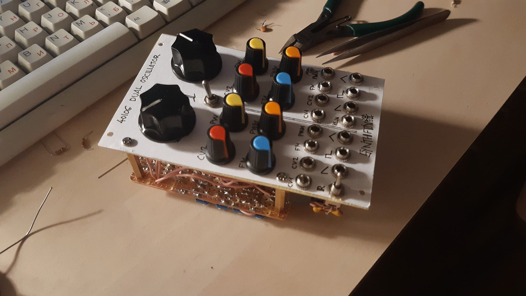
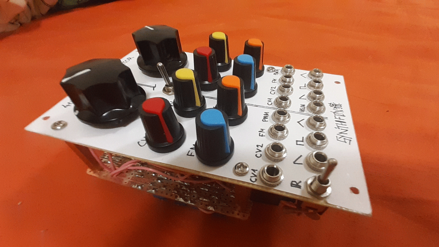
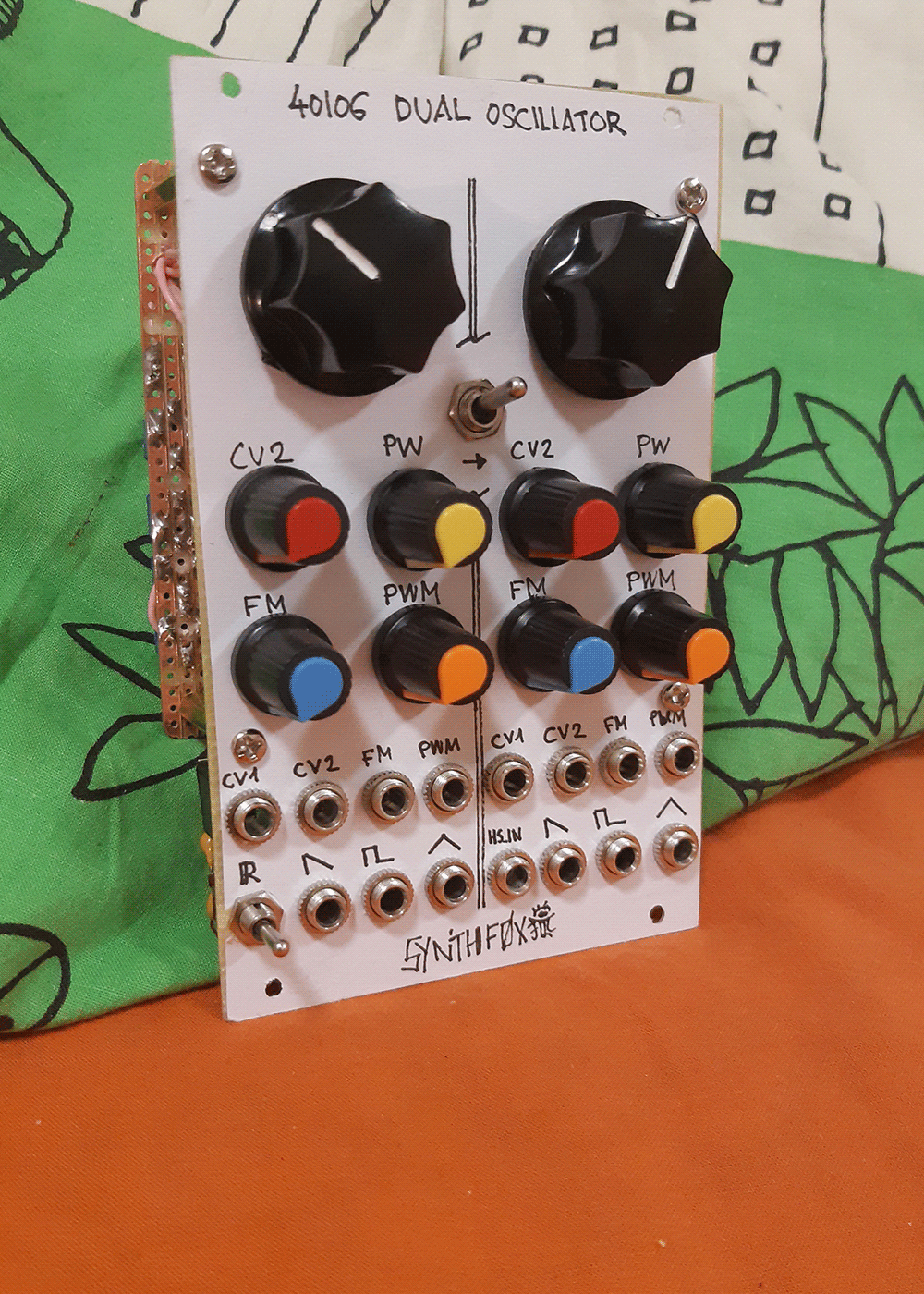
Pictures
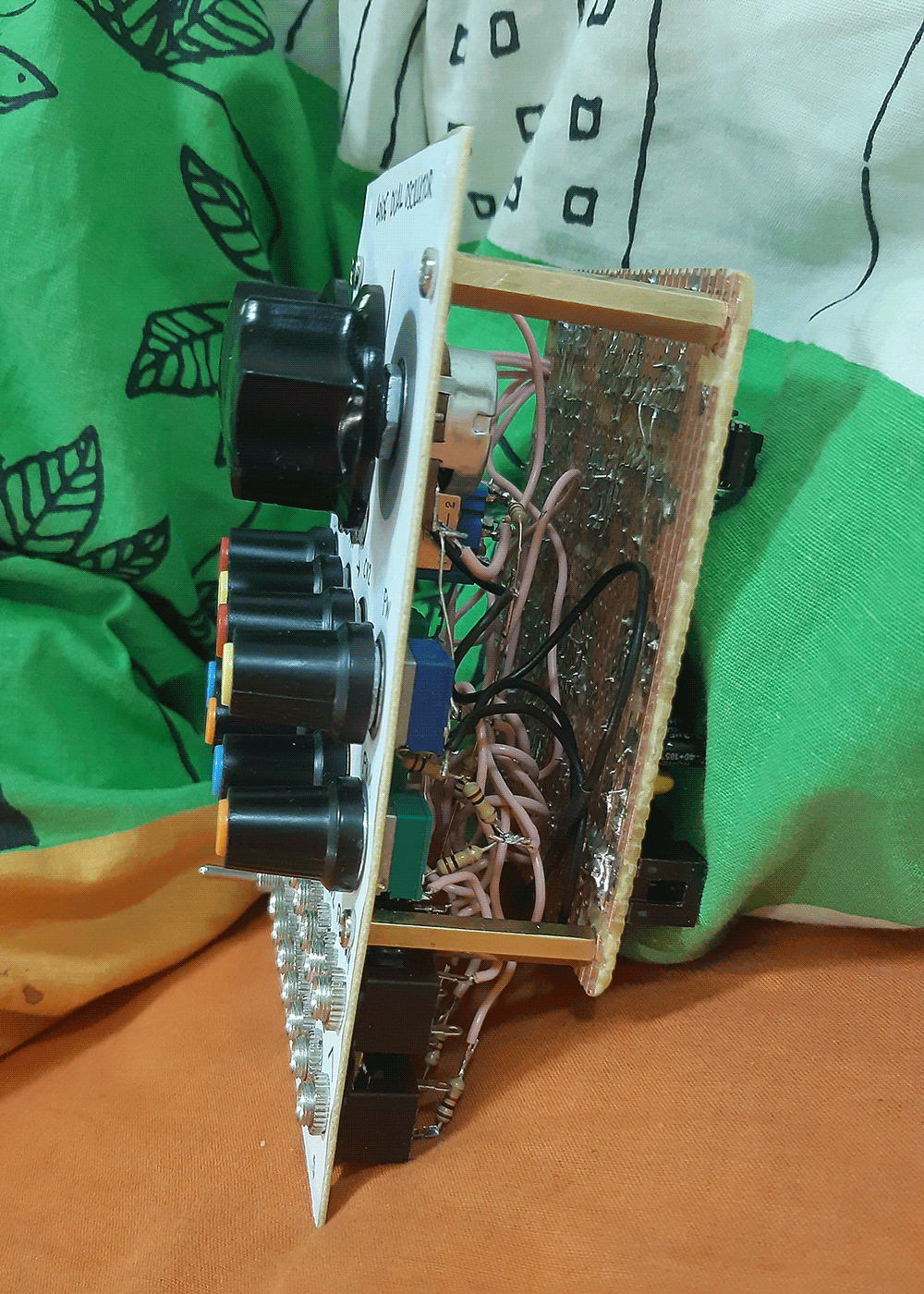
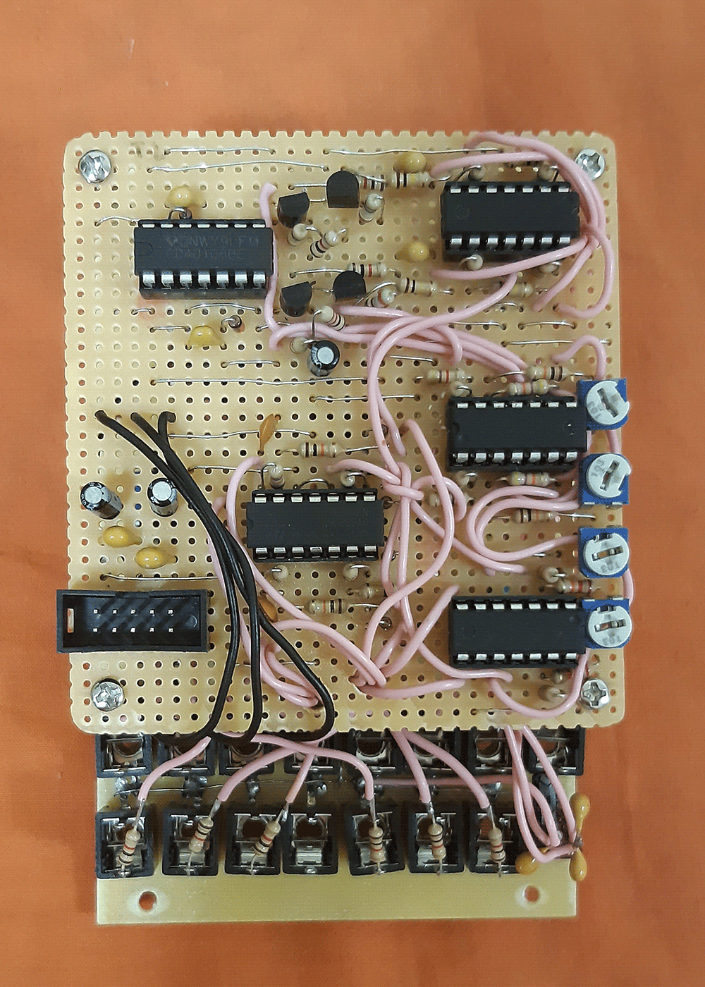
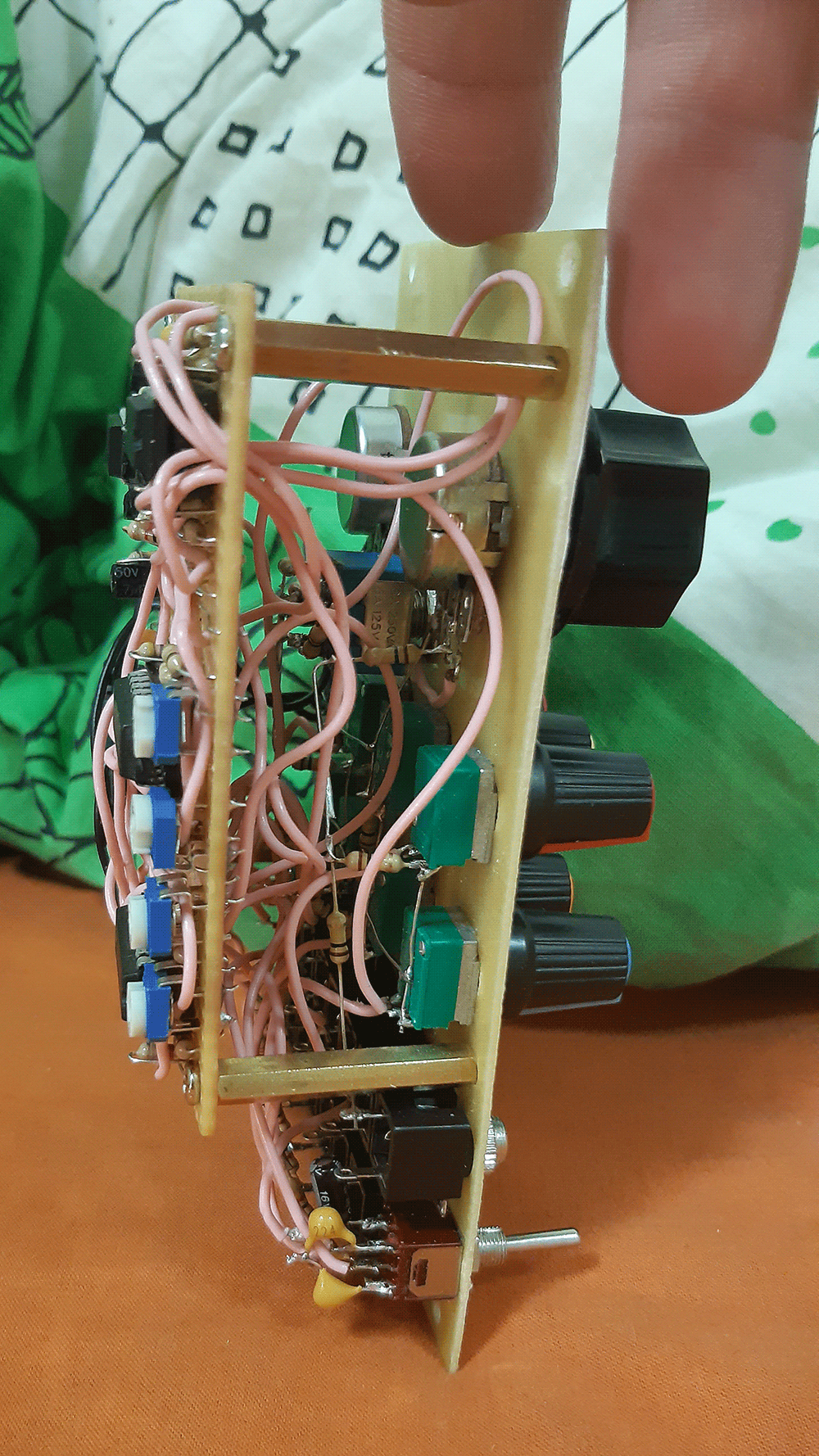
basmaster003's build