About
FAIR WARNING: this is a HARDCORE build and NOT A PERFECT design. It absolutely rocks to play with, melodic stuff included, but if you're searching for perfect volt per octave over the entire audible range, sterile FM tones, etc - this is not the place! I make tools for music, not test equipment.
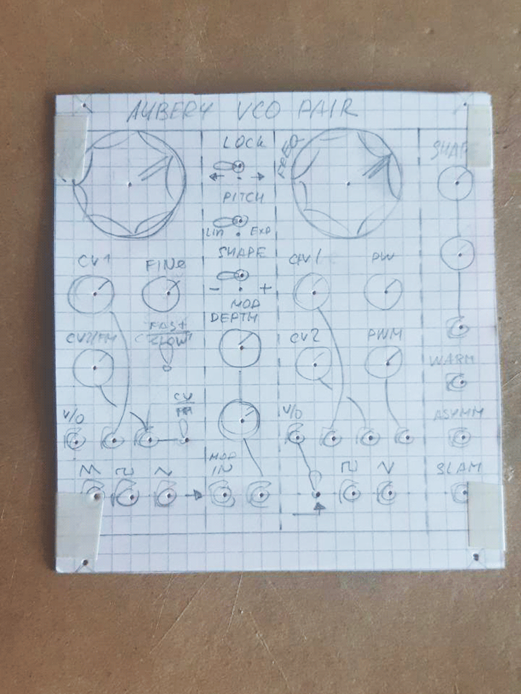
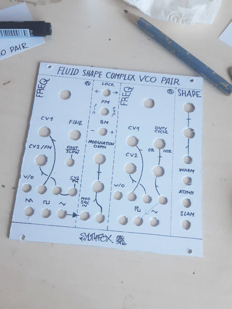
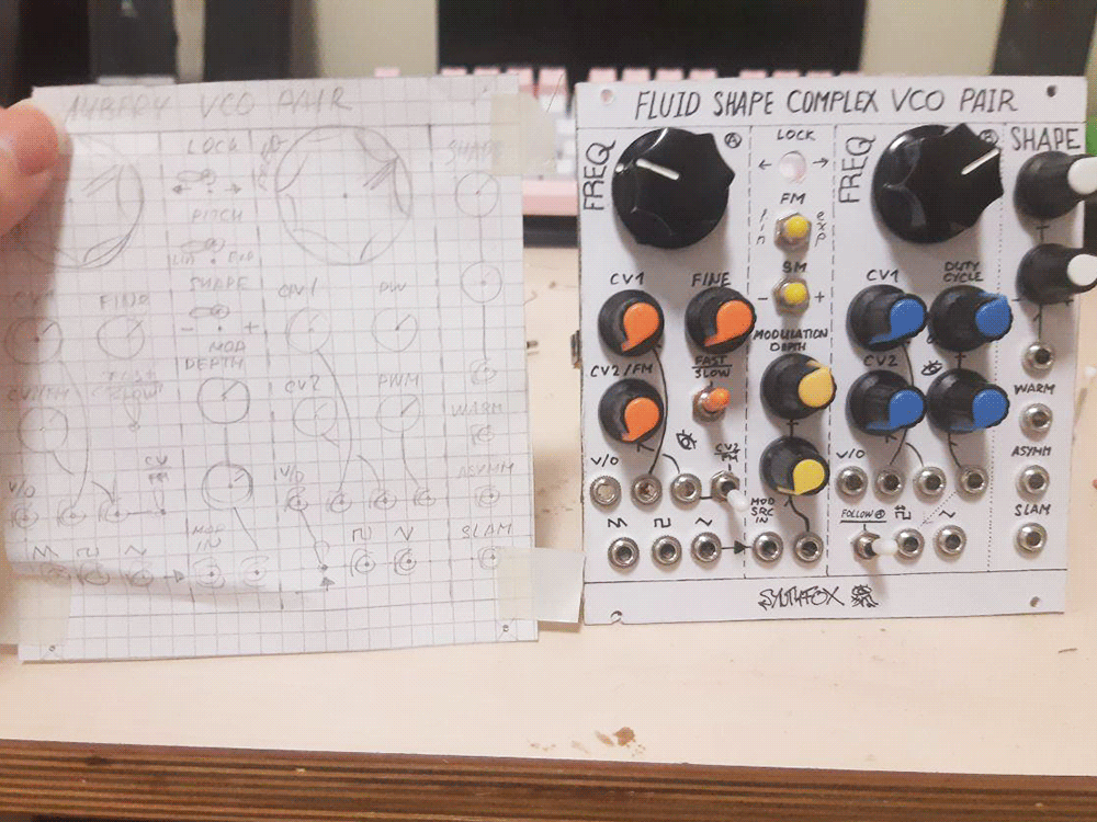
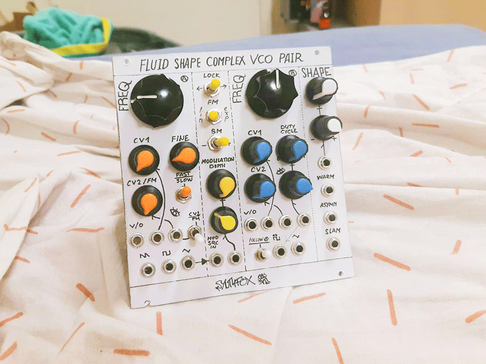
After being happy with how the vactrol-based Dual VCLFO operates, I decided that it can be possible to make it into a good exponential VCO if i replaced the vactrol with a proper OTA (operational transconductance amplifier) as a voltage-controlled resistance. One dream led to another, and, well, i designed a whole complex generator based on that idea. Obviously i wasn't the first one to think of such a VCO: it quickly turned out that Thomas Henry's VCO-1 uses a very similar principle, so i copied the current source + OTA of Thomas' schematic for the VCO cores. The module features two almost identical VCO cores, A and B, and a 'modulation bridge' - a quick interface to set up how much and how A affects B, and so on. VCO B is further processed by the Shape section to form three additional uncommon and 'fluid' voltage-controlled outputs, hence the name of the module. Although the combination of the elements (VCO 1 -> modulation thing -> VCO 2 -> some wavemangler) is not uncommon, the actual schematic and topology is not a ripoff of anything, and has quite a unique sound.
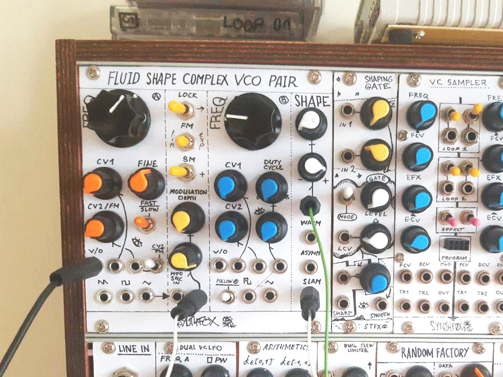
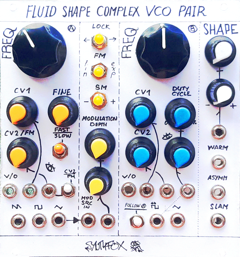
VCO A has a big initial frequency knob and two attenuated CV input. The second input can be either (exponential) CV2 or (linear, ac-coupled) FM, selected with a switch next to the jack. VCO B's triangle output is normalled to this CV2 input. It also has a fine tune knob (~6 semitones range). The SLOW/FAST toggle switch selects between VCO of the same range as B, and VCLFO of the "very slow" to "low bass" range. It also has a dedicated V/O input jack: both VCOs track quite decent 1v/octave and i was able to play it with a conventional volt-per-octave keyboard, although it goes sharp at lower bass and higher trebles. The output is a upside-down saw (mislabelled on the panel) an octave above the main tone, a triangle and a 50% square. The saw requires perfect transistor matching, otherwise it passes on some of the squarewave (my case). Nevertheless, it is a usable saw-sounding output.
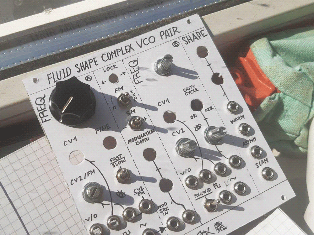
VCO B is similar to VCO A in many aspects. The difference is - CV2 cannot function as FM, no slow mode, no sawtooth output, but adjustable duty cycle (50%...0%) pulse with a dedicated attenuated CV input instead of a fixed symmetric square. VCO A's saw output is normalled to VCO B CV1 input for quick harsh crossmodulation. VCO B also has a very important switch called 'FOLLOW A', which, when set up, at the same time halves the range of its own big knob, and adds the CV sum that controls A to the mixture that controls B. In this mode, both VCOs are controlled with VCO A's knob/cv1/cv2 inputs, and VCO B's controls detune it from the pitch set by VCO A. This is useful when using them as a complex tone generator that plays melodies. VCO A's FINE knob only affects A, even if FOLLOW A switch is enabled on VCO B, for easy tuning when using the two VCOs as an FM pair.
The modulation bridge between the two VCOs has a modulation depth VCA at the bottom. It has an initial setting, an attenuated CV input, and a modulation source input. VCO A triangle is normalled to the input jack, so by default, VCO B gets modulated with it. The section has three 3-position switches. They all do nothing when in the middle position. The topmost, LOCK, 'locks' (formally neither hard nor soft sync, so i called it 'lock') VCO B to VCO A (set left) or vice versa (set right). This is handy to force the VCOs to stay more in-tune for the cost of added sharp edges in the sound, which often are very musical on their own. The FM switch routes the output of the modulation depth VCA to either dc-coupled exponential CV or ac-coupled linear FM input of VCO B. Usually, one would use the LIN mode when using two VCOs together in tune (or not), and EXP mode when using an envelope as a source and dynamically adjusting its amount with modulation depth controls. Finally, the SM switch routes either the inverted (-) or the uninverted (+) copy of the VCA output to the shape section control, along with its initial setting and CV input, making for an additional layer of complex modulation.
Finally, the Shape section on the very right of the module produces three waves of fluid, voltage-controlled shape. The topmost knob is the initial shape setting, and below is an attenuverted CV input. SM switch adds post-VCA modulation source to these two, if engaged. The warm output goes from ever-so-slightly harmonically enriched triangle to a full squarewave, but not by overdrive: instead, the squarewave 'expands' from the triangle's zero-crossings, making for a warm and pleasant movement. The ASYMM output is a voltage-controlled variation of the VCO A's sawtooth shaper that smoothly goes from an uneven sawtoothoid on the same note as the VCO to a slightly harmonized sawtooth one octave above. Finally, the SLAM output is an updated and minimized variation of Wavefolder Pro's guts, going from a bassy muffled triangle to a crazy over-wavefolded mess: naturally, my favourite. One of the fun things to do with the Shape section is to use its own outputs (or VCO B's own 'traditional' outputs) as CV input. It makes the already complex wave even more hecked up, which is, naturally, good.
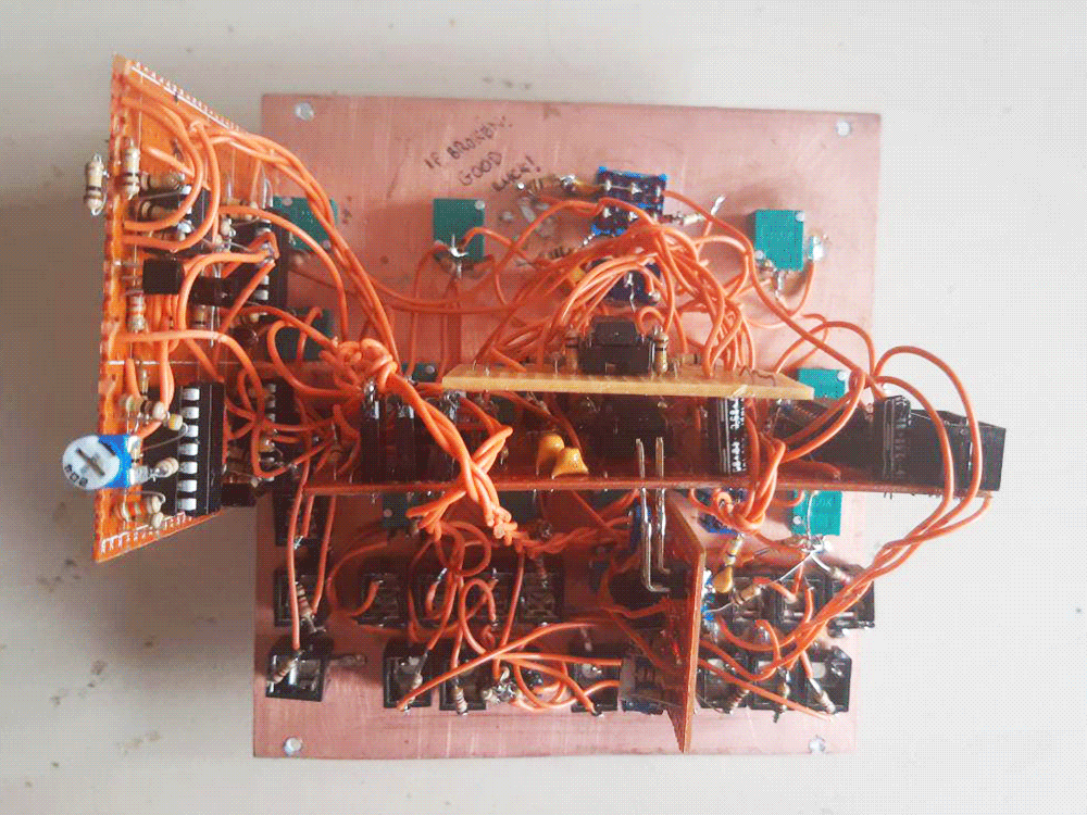
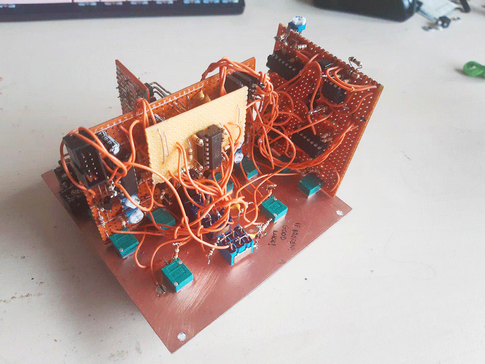
While this module does a lot and can go from melodic to harsh and abrasive in seconds due to efficient routing, the part count and complexity of the build is less than one would expect for such a thing, although still pretty complicated. To people closer to beginners than to advanced, i recommend checking out the way cheaper and simpler triple VCO design of mine, which also does a decent bit of volt/octave, and is the thing for harsher textures. To hotshots who actually are going to build this: send photos, i'm curious. Build this module block by block and test everything before mounting and hardwiring! I spent 3 days on this, idea to product, so i think it's possible to finish it in 3-4 days by the ready-made schematic. Good luck! The pain is worth it!
Schematic
UPD 27 SEP 2022: There were some value mistakes on the schem. Fixed. Likely no one attempted it so far. Still, sorry - my bad!
UPD 25 OCT 2022: R75 was labelled 100r - forgot to change it after copying from R76. It is, of course, a 1M pulldown. Fixed.
UPD 27 DEC 2022: This module's a hell lot of fun as it is, but its core elements have been improved and updated. Check this one for the better VCO core. The main difference is IC5B/IC6B are now an LM393 comparator, not an op-amp. For a better mod bridge VCA, check this design, it's also almost the same as here, but a couple parts make it a bit better.
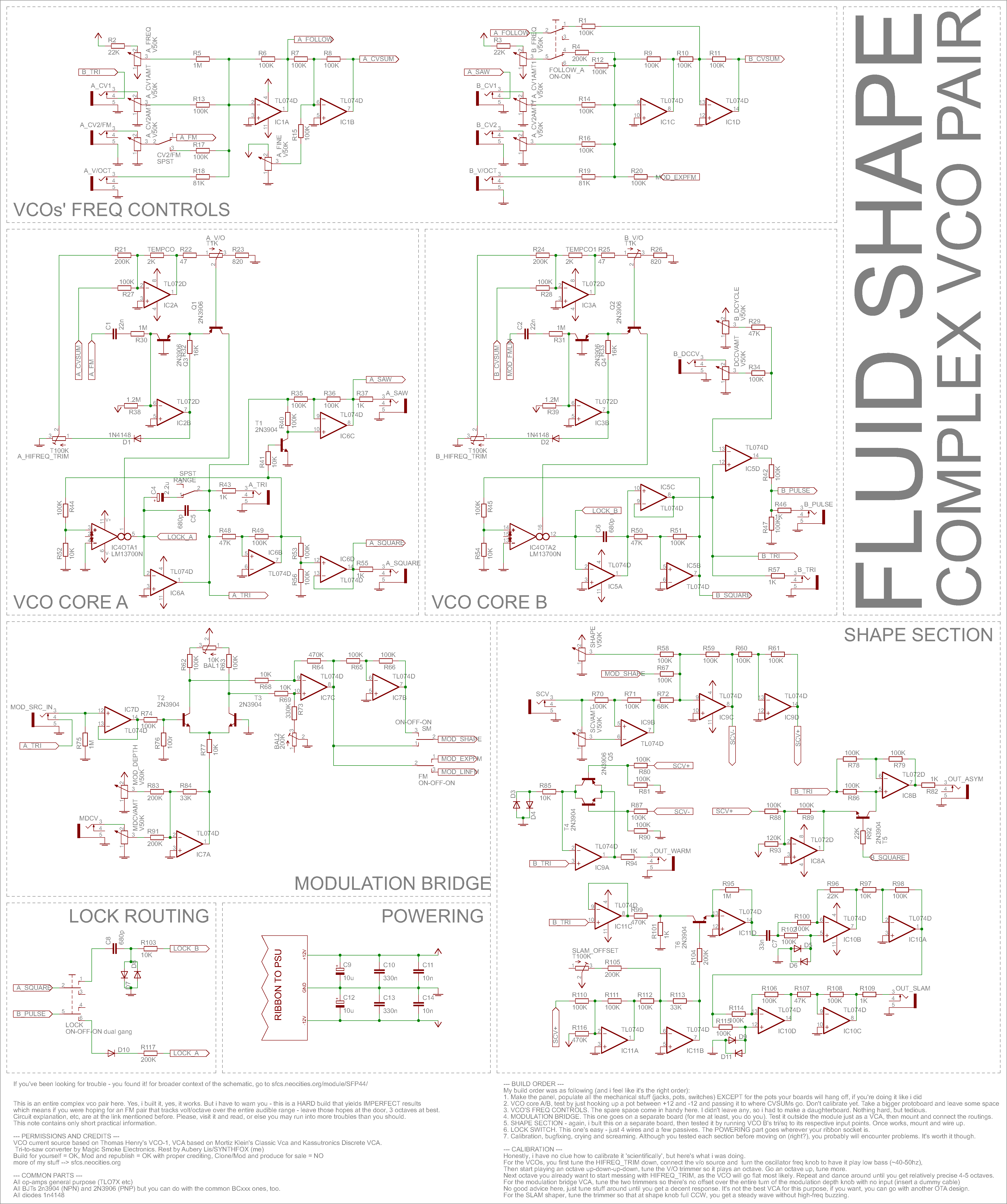
You will want to open the image up in the second tab and switch between it and the text! The schematic is not too complicated, but it will require some blabbing to explain. I will go in the suggested order of building the parts of this device.
We start with the VCO cores (A and B). They are pretty similar, and use the (very widespread and usual) "integrator + hysteresis comparator loop" principle of the aforementioned VCLFO to oscillate (IC6A/B, IC5A/B) with the exception of the resistor responsible for the oscillation frequency being replaced by OTA (IC4OTA1, IC4OTA2). Both VCOs have the same exact exponential current source driving the OTA: this article by Rene Schmitz explains very well about the exponential current sources. The design i used is by Thomas Henry, and features additional bells and whistles: a TEMPCO 2K resistor around IC2A (IC3A for VCO B), a hi-freq detune compensation trimpot, an FM input, and so on. Seems like i am misunderstanding something, because i had to lower the hi-freq feedback resistance ~20 times to be able to tune the VCOs nicely. My theory is that the comparator (IC6B, IC5B) is too slow and has to be assembled with discrete parts, like in Henry's design, to stay in tune at upper bounds. If you're feeling like doing things more properly, using VCO-1 design entirely is also possible, as they should sound fairly simple, but my design uses significantly less parts for the comparator for the price of slight tuning loss. For VCO A, the triangle is output unbuffered, the square is divided in half and buffered by IC6D, and a sawtooth is shaped with IC6C. Match A35/36/40 to be as close as possible with a multimeter in ohms mode to reduce the non-saw component. VCO B's trignale output is buffered with IC5C voltage follower, as it's used extensively by the shape section, and IC5D derives a pulse by comparing the triangle to the passive sum of the pot and the CV input. The CV attenuator acts a bit like a fine tune knob if no CV it patched in, due to the passive summing. Build both of these VCOs, don't calibrate yet, and leave at least 3x3cm space on the board for later. Test by hooking up a pot between +12 and -12v and connecting the wiper directly to A_CVSUM or B_CVSUM. Make sure the triangle output is there over the entire turn of the knob. Invest the time and match the transistors Q1/Q3 and Q2/Q4!!!
You probably noticed how instead of all the frequency knobs, cv jacks, etc, are not present in the VCO parts. Instead, a mysterious CVSUM is passed to the current source subcircuit through a miserable 100K resistor, and that's all. This is because some shenanigans have to be done to them before using them to control VCO frequencies, mainly for the follow switch to work. It is done in the topmost block, VCO's FREQ CONTROLS. On the left is the VCO A's controls. A simple double-inverting summator with IC1A/B for a good, no-crosstalk mixdown of incoming CVs and the initial frequency knob. Note how CV2 is routed with a switch after its attenuator to either contribute to the sum, or go directly to VCO CORE A fm input (find the same arrow on that block: this means they are connected. I could draw a wire, but things would get messy instantly). Note how the inverted sum is passed somewhere with the FOLLOW_A arrow. The FINE knob is wired between GND and -12V, so that the more clockwise it is turned, the more negative the wiper becomes. This is because IC1B is also an inverting summator that un-inverts the IC1A output, and since we don't want VCO A fine tuning to affect VCO B in follow mode, we don't want it to contribute to IC1A sum, we add it only at IC1B, and to produce positive offset at the output, it has to produce negative at the input (phew!). The IC1B output goes to A_CVSUM on VCO CORE A. It's perfectly fine to control the frequency this way instead of summing all the controls at the current source, and doesn't affect the performance. To the right is a similar circuit for VCO CORE B, that produces CVSUM_B with IC1C/D. The FOLLOW switch is a two-pole on-on, that either just passes the initial frequency knob through 100K (full range) in down position, or through 200K (half range) AND lets A_FOLLOW through. Remember how A_FOLLOW is an inverted sum? That's exactly why it is added to IC3D and not IC3C: we still have to uninvert it locally. The sum for VCO A controls also includes the output of the modulation bridge FM switch if it's in the EXP position. Naturally, i advice using 1% resistors for this part, as voltages on A and B have to be as same as possible for fine follow functionality, but i used 5%, cause i can't be assed, and it works just fine.
The modulation bridge is basically just a VCA and some switches. This VCA design is very usual, and i know at least two people (kassutronics and Mortiz Klein) who made their own versions of it. Mine is not very different and is closer to Klein's version. Modulation source is buffered with IC7D, just in case, and VCO A triangle is normalled to its input jack. Everything else is more or less textbook long-tailed pair VCA. It's nicely explained by kassutronics here. This VCA is, however, imperfect for CV usage, as no matter what i did, i still was unable to tune BAL1/BAL2 to produce exactly zero offset over the entire CV range. It is pretty much there, but does a barely audable smooth shift at init knob's noon. This doesn't bother me too much, but if you find this an issue, you can use another OTA for a more proper VCA. The long tailed pair's decoded output (IC7C) is further inverted at IC7B, and then there's the FM and SM switch. FM switch selects to either send the mod depth VCA output to VCO B FM input, or do nothing (middle position), or to contribute to the VCO exponential control voltage sum. Mind the switch type - if it's not a three-position on off on, you won't be able to NOT modulate VCO B!!! The SM switch is the same type, and it selects between inverted output, nothing and uninverted output, to be sent to modulate the fluid shape.
The shape section consists of a shape cv generator (top) and three separate processors (below). The shape cv generator is another double-inverting mixer with IC9C/D. The SHAPE knob goes from GND to +12v, so without any CV or modulation, SCV+ travels 0..12v and SCV- travels 0...-12v. The SCV input has a usual attenuverter circuit with IC9B, the result of which is summed to the SHAPE knob. The signal from the SM switch is also added here through R67. Below and to the left is the WARM shaper. Don't ask me how exactly it works: i experimented with transistor feedback and diode clipping, and found this absolutely precious circuit. Something something gain, something something BJT in op-amp feedback, really, i don't care and i don't know, higher deities whispered this circuit to me or some crap. It works. To the right of it is the ASYMM shaper, which is exactly the sawtooth shaper from VCO CORE A, but better: instead of dragging the IC8B + input to ground with T5/R92, it is dragged to a voltage set by IC8A in relation to SCV+. Pro tip: instead of using the (internal, otherwise unused) VCO B square, try putting VCO B pulse output to R92 for a funny castle-wall-shaped sound. It stops being asymmetrical then, though, so what's the point, if i already labelled the output ASYMM? Finally, there's the SLAM shaper, the most complex of all. IC10 and its surroundings form 2 stages of heavy wavefolding that works best with triangles, and they are not voltage-controllable per se. Howver, they react like crazy to change in the input signal volume. So i put together a crappy single-transistor VCA around IC11 that also badly distorts harmonically enriches the incoming triangle. It does get into buzzy bleed when IC11B output gets close to 0v, so the trimpot is there to provide offset: tune it so that you get a steady mellow tone at SHAPE knob fully CCW. I know i could use the same VCA as on the modulation bridge or even buy another LM13700 and make two 'good' VCAs for modulation and slam shaper, but doing the same thing that i already did and many others did, too, - that's just boring. On top of that, i tested the folding stages with a volume knob instead of the crap VCA, and it just doesn't sound as slamming as with the crap VCA.
FINALLY, the lock switch! I propose to mount it the last because it's just 4 wires and some passives that otherwise will be dangling around, disrupting your debug, but you do you. It should be a two-pole on-off-on switch. In the middle position, nothing locks to nothing. In left position, VCO B pulse output is passed through D10/R117 to where the LOCK_A arrow brings it in VCO CORE A: the - input of the integrator, the heart of the oscillating process. This is a very rough harder-sync that turns off the oscillation while the pulse is high. The VCO B duty cycle controls will affect how this locking sounds. It's best to use this locking when VCO B runs lower than VCO A, for wheezy filterlike FM. In right position, the switch puts VCO A squarewave through a funky passive setup, and to the same integrator opamp - input on VCO B. This is some WTF kind of a sync: not exactly hard, not soft for sure, and sometimes it 'misses' in a nice way, but it does its job. This is what usually gets engaged when VCO B is running higher than VCO A for classic FM tones and wicked SM. Locking also helps the two VCOs stay in tune, or with some settings - bring out some harsh distortion out.
CALIBRATION
For VCOs: connect your 1v/o source (e.g. arturia keystep) to the v/o input, turn off all the internal modulation, then tune the HIFREQ pot fully towards the ground. Bring the oscillation to 30-50Hz with the main freq knob and start playing an octave on the 1v/o cv source. Tune the V/O trimmer till it actually plays an octave. Go an octave up on the CV source, play the same octave again, tune V/O. Repeat the process, but now your main tool is HIFREQ_TRIM - mostly use this, and do minor adjustments to V/O. Check the scale over different octaves, retune if unhapy. You should end up with 4-5 octaves of tuned scale eventually.
For the modulation bridge VCA: no clue what to say here. Connect a dummy cable to MOD SRC IN, enable exponential FM on the bridge, put the VCO B freq knob to noon and listen to its triangle output. Turn the modulation depth knob there and back, and you will notice the change in VCO B's pitch. Mess with BAL1/BAL2 until you get as close to no pitch drift over the cours of the entire knob spin.
For the slam shaper: don't modulate anything with anything, bring VCO B to middle frequencies, monitor the SLAM output. Tune the trimmer so that with the SHAPE knob fully CCW, you get a mellow trianglish wave without a buzzy/spikey component. Or i mean, keep it if you like it.
Some general advice: don't rush, be careful and check with the schematic often. I checked the schematic many times, but if you see something weird - don't hesitate to ping me somewhere (analogpatch@gmail.com for example). Build it block after block, fully test (but don't calibrate unless that's part of the debug 'what if') each block before installing. Be careful with your veroboards - don't drop them, check for shorts, use plenty of flux. Drink tea and listen to good music, cause this build is long and somewhat exhausting. And, of course, only take on this build if you want to build something yourself, have fun while you build and while playing, but not if you just want a cheaper complex waveshape generator.