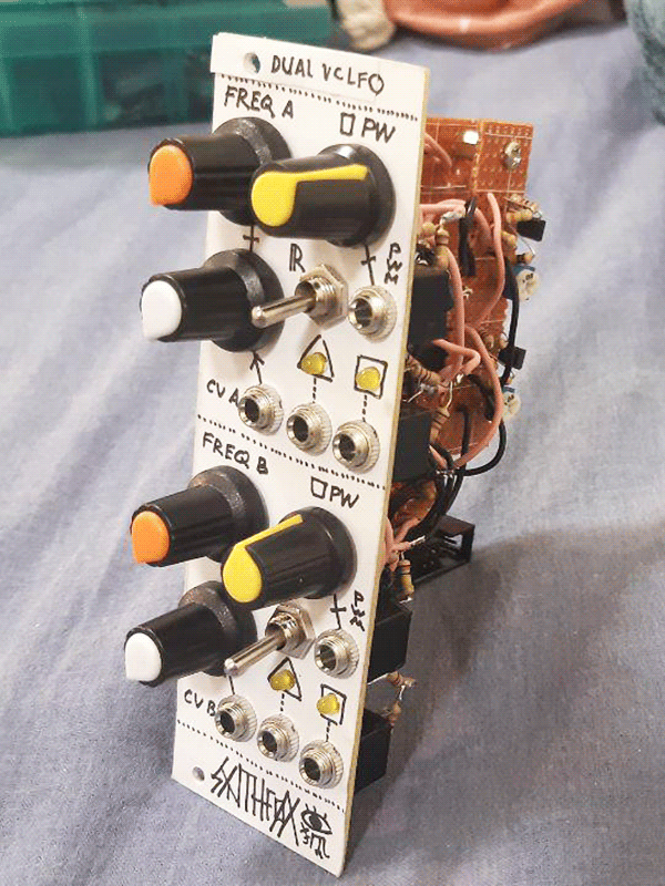
About
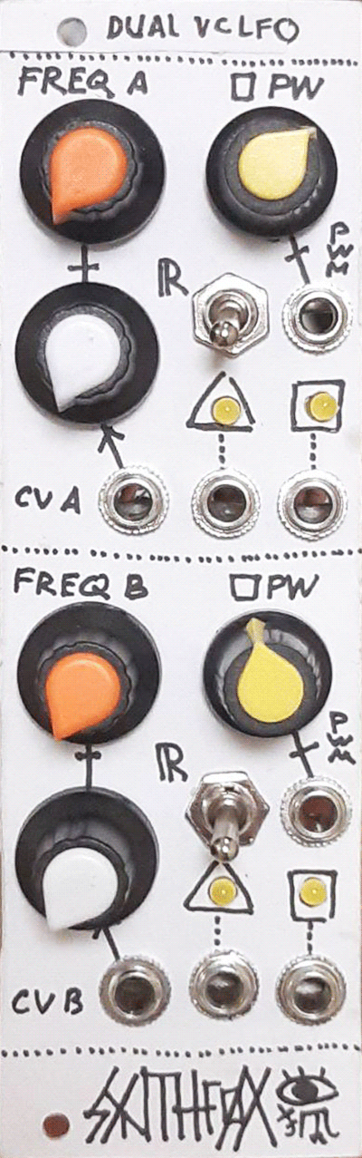
A lack of simple cyclic modulators in my SDIY system and my will to create designs that can be built by lower SDIY level people got into superposition and led to this module being made. This is a dual voltage-controlled LFO with a fixed waveshape triangle output, and a pulsewidth-modulated pulse output. Each LFO features a frequency knob, one CV input with a dedicated attenuator, a PW setting and a PWM jack for the squarewave output, and a range switch to select between low and audio ranges. The design is extremely simple and the voltage control is implemented using a vactrol for the easiet and fastest build possible. This LFO has a great range, and a good enough cv-frequency response for such a low part count. The design is highly customizable and can be recommended to people who just finished being full beginners and want to build something a bit more serious than an atari punk console.
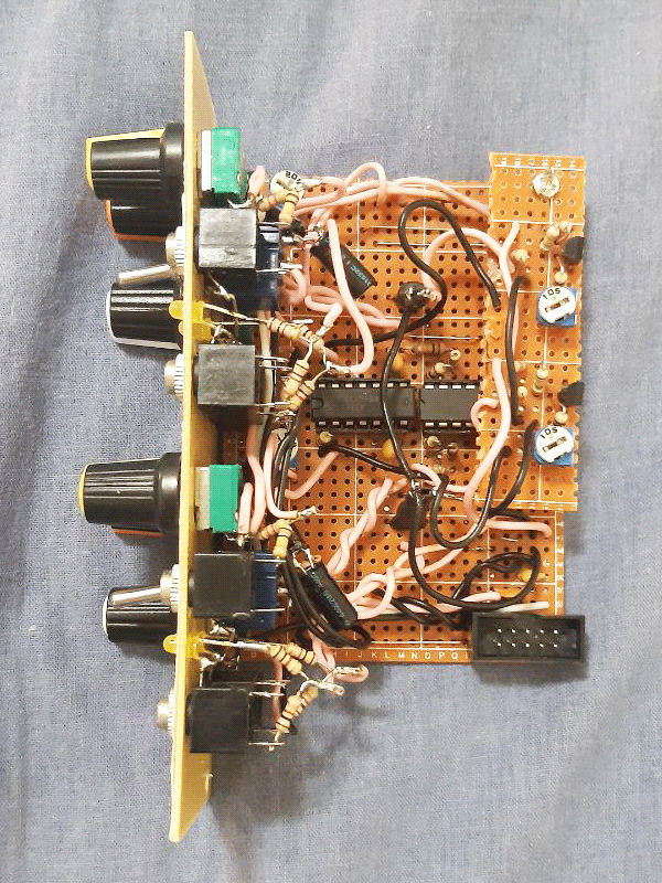
Schematic
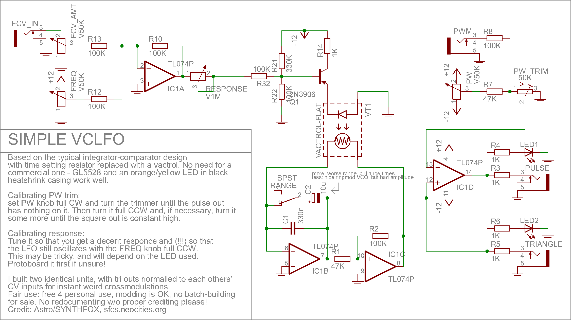
The schematic builds on the most basic concept of an LFO using an integrator (IC1B) and a hysteresis comparator (IC1C). I will describe its workflow here - if you already know about it, skip to the next paragraph. Suppose the output of the comparator is high (a bit less than +12v). It starts charging one side of the capacitors C1/C2 through the feedback loop, which means the integrator op amp will do its best to inverse-mirror this charge on the other side of the capacitors, thus the integrator voltage output will start sliding down. While the comparator's inverting input - is grounded (which means its output goes high when whatever is on its non-inverting + input is above ground and low if it's below), the non-inverting input + sees a sum of comparator and integrator outputs through resistors R1 and R2. Since the comparator output is high, it shifts the overall voltage sum at + up, which means the integrator output has to go a few extra volts down to cross 0v (ground) to compensate for it, rather than just drop to 0 itself. When it does so, the output of the comparator flips low (a bit more than -12v), so it discharges the capacitors' right sides => the integrator charges their other sides and its out voltage goes up. But again, to cross the ground and flip the comparator, it has to now go a few extra volts above zero to compensate for the negative shift introduced by the comparator output thorugh R2. When it does so, the cycle completes, and we get an oscillation - triangle at the integrator output and square at the comparator output.
This kind of comparator that force-shifts its input with its output is called a comparator with hysteresis, and in essence it has two different thresholds - one to make it go high, and another to make it go low. Read more about hysteresis comparators - they are very useful in many fields of musical and non-musical electronics!
Now, this is all cool, but voltage control, range switch and pwm? Well, the voltage control is done almost the crudest way possible. Take a vactrol and slam it in there - its resistance will define the rate at which the capacitors are charged or discharged. Don't have a vactrol? Use a GL5528 light dependant resistor and an orange/red/yellow LED and put it in black heatshrink tubing, which is exactly what i did. IC1A does inverting summation of the frequency knob and the CV input, so, the LED is reversed in order to save another op amp for PWM. In order to drive it, a little transistor circuit is there: R21/R22 shift the sum down a little so that there's no "dark zone" on the first 20% of the frequency knob, and the transistor improves the freqiency response a bit. Range tune trimpot is a bit tricky: too much and you start offsetting the LED, too low and the frequency knob does nothing from noon position till full CW. Tune it so neither of those happen. If you don't like all of this and want to go even cruder, just slap a 1K resistor and a 10K trimpot in series from the op amp output right to the LED and tune to taste. This will work worse, but it will work.
As for the range switch - a simple single pole single throw switch is enough to add/remove C2 in parallel to the small capacitor C1 around the integrator. Its value can be any value from ~3u till ~100u, but 10u had the best range to my ear; my next pick would be 22u for true ambient LFO speed, but still some sort of range flexibility. This mod can be eliminated completely, leaving only C1, but then C1 would have to bee in ranges of 10s of uF to have this VCLFO in VCLFO ranges.
Although we can derive a square output right from the comparator output, i decided to use the op-amp i saved on the frequency voltage summation for some janky PWM effects. All it does is compares the triangle output to a passive sum of the PW knob and the PWM input. the PWM input in my case does subtle modulations, as it doesn't have a dedicated attenuator. If you want to, you can add one, or change R8 to something like 47, or evern 22 kiloohms for sharper external control. The pw_trim trimpot is there to tune the range of the knob. The triangle output oscillates symmetrically around zero, so it makes sense to tune it so that the PW knob makes the output go constant high when full CW and constant low when full CW. The LFO frequency WILL affect this output a bit, so test your setting at various frequency knob positions! Swap the + and - inputs places if you want an inverted pulsewave (full high at PW full CW, full low at PW full CCW). Also, by the way: the LED indicator for the triangle output will only show half wave if grounded. I don't mind it that much since it's just for activity indication, but you can buffer it with another op-amp as a voltage repeater, and then use two leds in different directions to show it going above and below zero.
Finally, a bit on crossmods. The circuit shows one unit - i built two identical units in one panel. I then took the triangle outputs and put them to the normaled signal leg on each others' CV jacks. This means if nothing is patched into the CV input, the other LFO's triangle is there. This allows for instant insanity. The LFOs do have a slight drawback, though - at least for me they did interfere a little, when both are in high frequency range. Most likely this is because i received an absoltuely terrible batch of TL074 op amps: 3/4 of them are non-functional, and others behave weirdly sometimes. I'm sure quality parts will assure minimal interference.
Media
Basic demo of the triangle output, frequency range in low and then high range switch settings.
When the pulse output is self-patched into the CV input, the LFO shape can start resembling a rising sawtooth. Play around with PWM and modulation depths for various shapes! Inverting the square output will make it a falling sawtooth.
Manual and external control of the pulse output pulsewidth
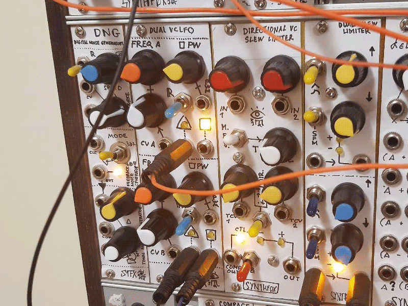
FM pair, the VCOs are unkinked and each is controlled by a separate LFO. The internal cross-mod path on the Dual VCLFO is used to create more chaotic behaviour.
Full demo patch with crossmodding LFOs controlling FM depth, waveshape, output to delay volume and a squarewave is shifting the delay time.
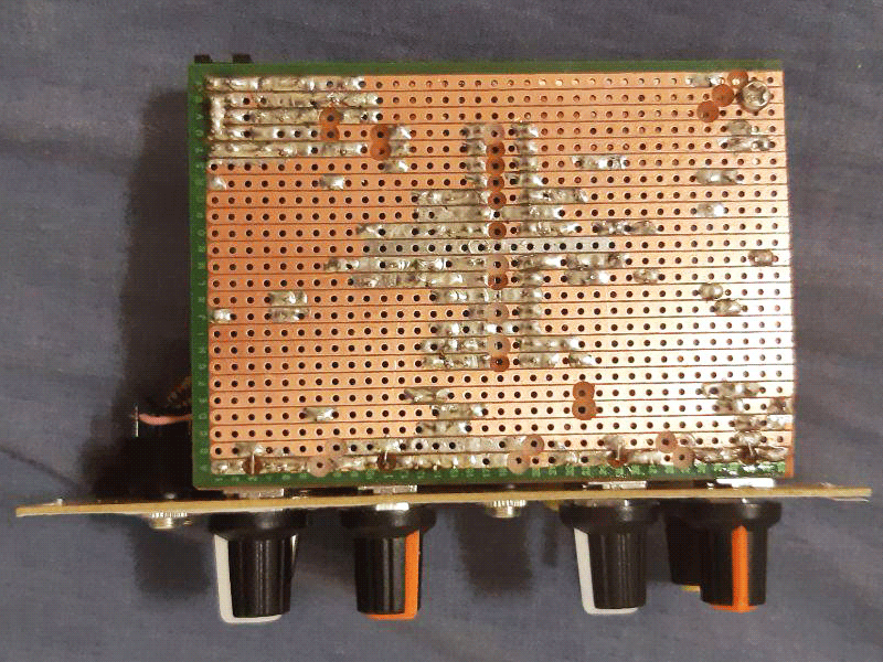
Pictures