About
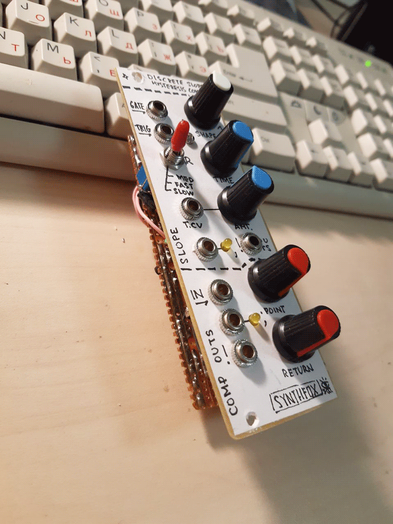
This here is a 'double module' - two completelty separate and different functions in one panel. Yet they go very well together!
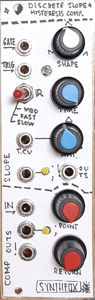
The more complicated, upper part is the Discrete Slope. Basically, it is a result of me thinking "why op-amps? I will make a function generator purely out of discrete components, and everyone can eat my shorts!" and winding up with something not quite what i wanted, but still quite an interesting quirky attack-release envelope generator. It has a time control and a shape control. Time setting controls the length of the overall envelope cycle, excluding the time when the gate is held high after the output reached the peak value. It is CVable. Shape controls the attack and release time proportions, going from an instant jump up and slow release, to equal attack and release, to slow attack and insatnt dropdown. Gate input is for (you guessed it!) gating the envelope, and trigger envelope is basically gate but if you badly want those sweet krell pluck envelopes - it works a bit weird. There is a normal and inverse output of the resulting function: the inverse one is acquired with a cold and uninteresting op-amp offsetting inverter, though: wanted to keep all aspects of the waveshape in the inverted copy. The normal output has a control LED, the inverted is just there.
The bottom part is a comparator - thanks to a DIY person of the New York Modular Society chat, it has a so easy to install but so necessary feature - the hysteresis control! The point control sets the comparator threshold T, and the return setting sets a certan voltage H. Then the input signal is compared with T+H volts if it is rising, but with T-H volts if it is falling! Why is this cool? It provides a very nice hysteresis 'window' handy for, say, extraction of probabilistic gates from a noise source, or it can be an interesting PWM wave extractor for a complex waveshape - and sometimes, you need it to make things cycle! Such as the case with the slope generator above. Connect the inverted output of the slope to the comparator's input, the inverted output of the comparator to the gate input of the slope, find a sweet spot of the point control - and you get an LFO with a shape control, 'smooth' outut from the normal slope output, and pulse output from comparator's normal output.
These two are very quirky circuits, especially the slope, and so far i had success using this module as a subharmonic divider, a filter, a distortion and an LPG, among other, more trivial uses. Very interesting thingy!
Schematic
First off... you want to open this in a new tab or download, and zoom in. Despite being simple, this circuit is long as hell! Secondly - a little disclaimer here: i have no idea how it works. Don't ask me! I have some kind of esotheric, shallow understanding of how BJT stuff works, so it's a miracle that my hot take and funny joke turned out to be a working unit. It was hard to make it, it is super strange, and i had to rebuild it about 4 times block by block. If you decide to make one - breadboard it first, for the sake of everything. I know that i included the veroboard layout in the build materials archive. Don't trust me! Breadboard it! Even though the layout seems to be fine. OK? OK.
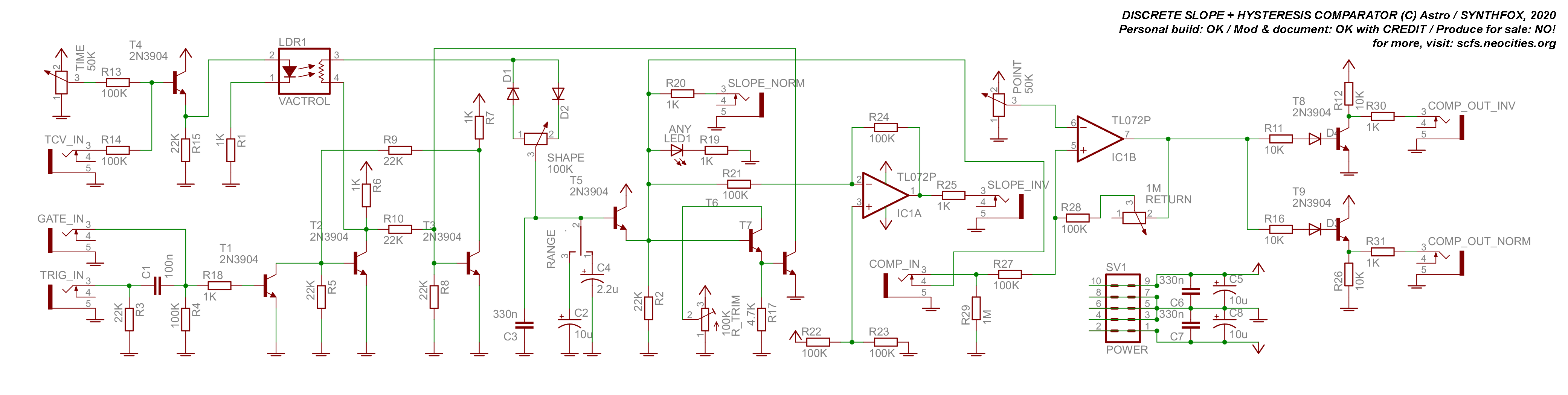
The core of the slope circuit is a flip-flop made out of two transistors T2 and T3, and the bunch of resistors around them. Basically if you apply a ground to one of the transistors' bases, the voltage at its collector will rise up to some voltage, and on the other's collector it will fall to almost 0. It will stay this way until you take the other transistor's base to the ground, which will mirror the collector voltage situation.
Then we have T1 and all the resistor-capacitor garbage before it as our gate input: when we gate T1's base, it opens and brings T2's base to the ground, putting the flipflop into the state when T2 has high V on its collector, and T3 has almost 0V on its.
T2's collector is passed through a DIY vactrol (GL5528 recommended as the photosensetive element, and a red/orange LED for controlling it). T4 and its surroundings act as a summator for an initial time value and the time CV input, and the vactrol's LED driver. After the vactrol's resistor part, the signal from T2 collector passes through the two diodes and a potentiometer, which kind of chooses which way do we charge/discharge the capacitor after it quicker, and which way - slower. It is the shape control block. Together with the following capacitors-to-ground and T5 voltage buffer, this whole path from T2 collector to T5 emitter is a vactrol-controlled slew limiter, basically.
This would be good and fine, but we have a problem: once we put a gate to this circuit, the flop will jump up, the slew will slowly catch up to T2 collector voltage, and it will stay like this forever! There's nothing to pull the T3 base to the ground and flop the T2 collector voltage back to 0. And for that is the T6-T7 path: T6 acts in a comparatorish way and T7 pulls down T3's base just as T1 (our gate processor) pulls down the T2's. There's a little catch though, the trimmer is very touchy! First set it to zero volts, then put a gate to gate in: the slope output will rise and stay high. Slooooowly increase the trimmer's voltage until the moment it falls back down. Test it a few times: might need a few more tiny nudges to the +V side.
All good! Now the normal output and the indicator LED's signal are taken directly from our voltage buffer T5's emitter, and the inverted copy is made via the offsetting inverting op-amp.
The comparator part is much much easier to understand: just search the Web for 'hysteresis comparator op-amp' to read more on this, but basically this is what happens when you have virtually infinite gain and automatic offsetting of the input depending on the output. The output is bipolar, so i put two transistor logic buffers - inverting and non-inverting - to get two unipolar (doesn't go negative) outputs from it.
POSSIBLE IMPROVEMENTS: Add an attenuator, an offset knob and an offset input to the comparator's input by strangling them to the + of the op amp through 100K resistors. Replace the RETURN potentiometer with the same vactrol setup as for the time setting. Add an offset in jack to the point potentiometer (needs to replace the direct connection to the 2x 100K resistors passive mixer of the knob and input). All of this will make the comparator one hell of a probabilistic gate machine hungry for noises and complex LFOs. I didn't implement all of these for the sake of simplicity. Maybe there is an exquisite non-vactrol way of controlling the time of the slope? Something tells me there is... tell me if you find it! The diodes+potentiometer thing could be replaced with the Serge VCS's transistor core, potentially making this thing have separate attack and release VC-controls. Go nuts on it! (but don't blow anything up)
Media
the Doepfer A-110 square through A-102 diode VCF. Slope cycled through the comparator as described above and used as an LFO for cutoff frequency of the filter.
Two pluck envelopes control the A-102 VCF. One is triggered with the same clock as the sequence, the other is trigerred by the result of passing the clock through the slope and comparator combo. The slope slews down the clock, and the comparator then extracts a slightly delayed clock out of the slope. An LFO controls slope's Time setting, making the trigger delay fluctuate back and forth.
A squarewave, and then a triangle wave of an A-110 is put to slope's gate or trig in (range set to fast), inverse output passed to the comparator, comparator output put back to slope's trig or gate. Audio output is the slope normal output. An LFO made on the Directional VC Slew Limiter is controlling the Time setting.
Standard white noise (Doepfer A-118) put to comparator in, the normal output to Serge 73' VCF in, inverted out to that vcf's cutoff CV in. Playing with the Point and Return settings to control both the evenness and the density of the random gate stream!
Showcasing the most obvious usage here! A-110 FM pair sequenced by my step sequence programmer, sequencer's clock divided and rotated by 4MS RCD and passed on to the slope. No voltage control here: just twiddling the knobs on the slope module.
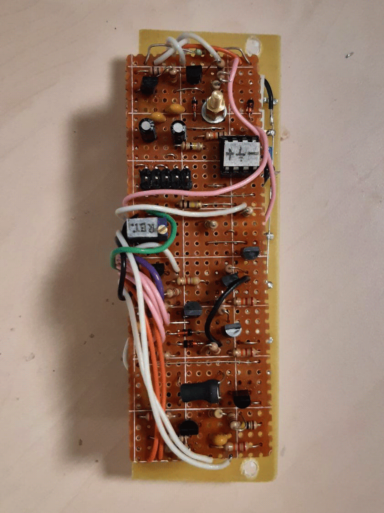
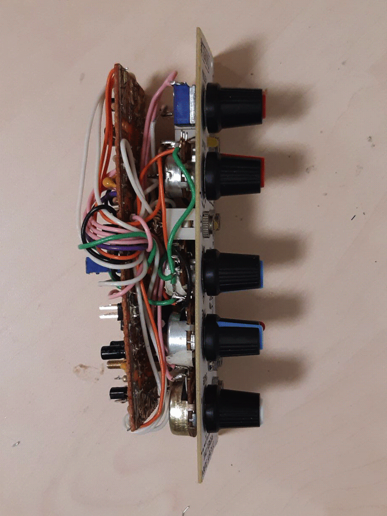
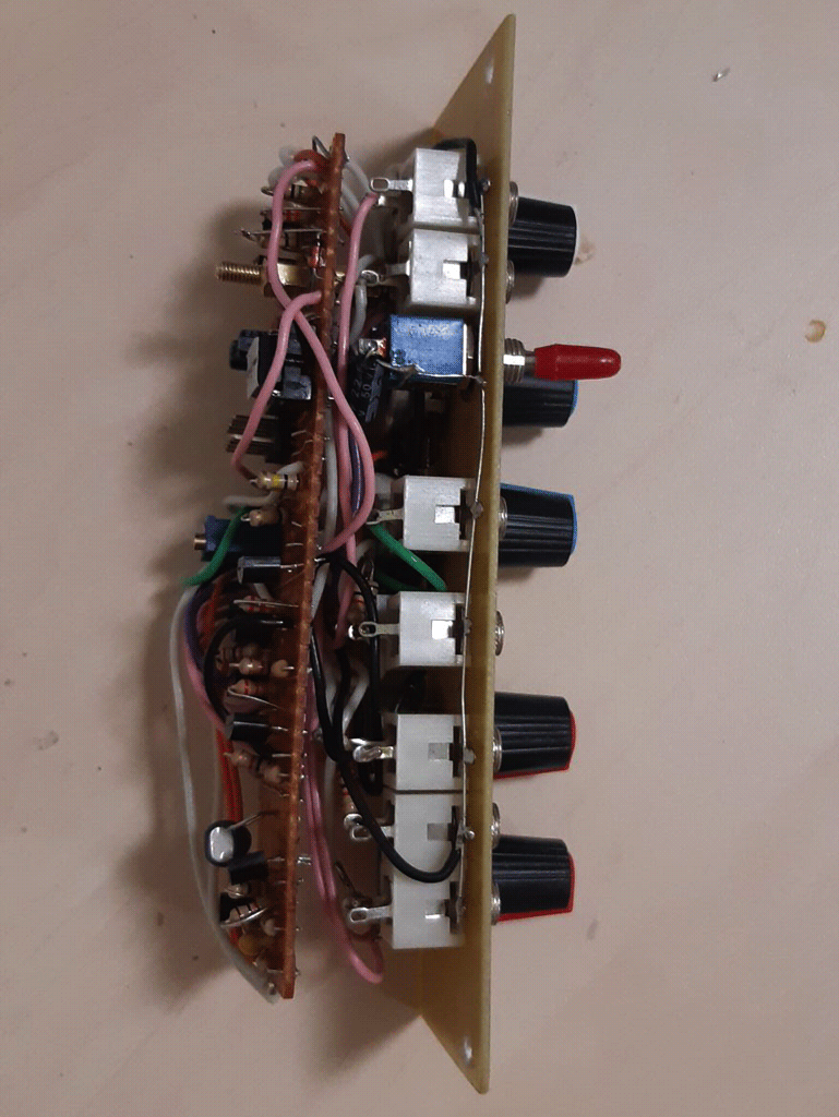
Pictures