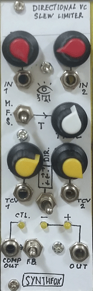
About
The DVCSL (Directional Voltage-Controlled Slew Limiter) is an original circuit - a huge expansion on the very basic concept of an op-amp based slew limiter/lag processor. It can convert squarewaves to triangles, triangles to squarewaves, noise to random gates, nice sounds to extremely folded mishmash, be an envelope follower, a filter/gate, be a VC LFO or a VCO, a clock generator, and many more things inbetween and beyound!
The most basic purpose of this module though is to "smoothen" stepped signals: when a step in voltage happens (say, there's a squarewave LFO at one of the inputs) the output will glide towards the new input voltage. No matter how many volts the input signal has 'stepped', the glide time will always be the same and is determined by the sum of the two Time CV inputs and the TIME knob. Span of time settnigs is adjusted with the Range switch from slightly audable glides to medium to very slow, barely moving glides. This allows to use the module on sound signals, as well as CVs.
UPD 21 MAR 2022: although this design is 'logically' easier to understand (a usual lag processor + a vactrol), i did eventually make a vactrol-less, way better design. it's a bit harder, but way better. One lag processor from the new design is more or less equivalent to this unit. However, vactrol time control has its quirky upsides, so if you're in for that - keep on reading.
It can, of course, process any kind of signal - not only the stepped ones. Describing how it would react to other types of waves is a bit hard, but generally it will always try to 'smoothen' up a wave - like a low pass VCF (in fact it is one), but for CVs as well as for audios! A handy feature for making your waves even more 'custom' is the Direction switch: in the middle position it doesn't affect anything, but in up and down positions it will nullify the raise OR the fall time of the output - so when the input goes up, the module does its job - but when it's falling down the output is not affected by the filtering network (or vice versa). You can have your sequencer, for example, glide only when the note is higher when the previous one, and drop to a new lower note immediately.
Finally, the last peculiar feature of this slew limiter is what i call 'cycler comparator' - in fact, it's two comparators: when the output crosses the upper threshold (1/2 positive supply) in upgoing direction, the COMP output drops to 0v. When the output crosses the bottom threshold (close to 0V), the COMP output rises to +VCC (CMOS logic 1). The most basic thing you can do with it is feed it back into the signal input - the module has a handy switch for it - and you have a VCO! Its frequency is now defined by Time parameters, the range can be selected with the range switch (from audable VCO to fast LFO to really slow LFO), and the shape can be selected with the Direction switch - you can get: rising saw, triangle and falling saw. You still have two unused signal inputs though, so why not to use them?... basically what happens now is already considered 'crap diy synthesizer magic' by me and i have no clue how it works, but with VCOs it starts behaving like an extreme wavefolder/filter and whatnot, sequences start getting random wobs here and there, and so on, and so forth. Experiences may vary! Another tip and trick for the COMP output is to leave it unfeedback'd and use it to compare the input signal to preset voltages in a weird way. The most fun is to put a noise source to the input and adjust the volume so that it 'touches' the comparators just sometimes - you will end up with a random long gate generator!.
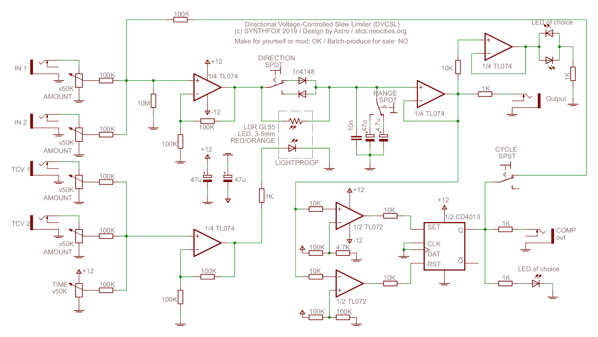
Schematic
Funnily enough, this device has a very straightforward and simple design. It's based around a typical fixed slew limiter (op-amp buffer - low pass filter - op-amp buffer), but i made a tiny bit of improvements.
First buffer is replaced with a unity-gain non-inverting summator which mixes down two signals and - if the feedback (cycle) swtich is on - the COMP out. Secondly, the passive LPF's resistor is replaced with a light-dependant resistor (LDR), the GL-5528. The same summator as for input signals sums two Time CVs and the initial Time setting - the resulting voltage drives an LED packed in a lightproof casing next to the LDR's surface - we get a homemade vactrol, and now it controls the slew LPF cutoff!
Around the LDR there's a switch that can short out the LDR when the capacitor either charges or discharges, this activates the downwards or upwards mode. Note that this switch should be double-throw (with a middle OFF position), otherwise you won't have a bidirectional slew option! Another switch is added next to the LPF capacitor - it adds another capacitor (one or the other) in parralel to the first one, increasing the overall capacity. This is the Range switch. It also has to be double throw.
The second buffer is left untouched - just a voltage follower. It then passes the signal to the LED driver voltage follower and the two op-amp comparators on the bottom, which then set/reset the CD4013 dual flipflop. This is what forms the COMP output.
it's a tricky circuit that acts like a kind of inverted artificial hysteresis, meaning that when the voltage at the comparators block crosses an upwards threshold the output 'turns off', and when it crosses the lower threshold on its way down the output 'turns on'. If the output is fed back to the input, we get a loop: comparator output is high, it makes the slew output rise and cross the upwards threshold, comp out gets low, slew slides down, crosses the downwards threshold, which turns the comp out high again, and so on and so forth.
The circuit is very plain and easy to comprehend, but that comes for a price: a vactrol will always have some resistance (about 10K at full light) and thus you won't ever be able to CV from a slewed signal to the original signal, as it may be possible on some VC slews and slope gens. It also prevents Time FM higher than some certain frequency - LDRs have a bit of inertia and narrow out fast signals at some point. But the circuit acts very interestingly because of the vactrol, and for such a wonderful piece of gear which is that simple it's not a big deal, i thihk.
Media
Sequencer CV put through the module, then to VCO PITCH CV. Time slowly modulated by an LFO. Note how the s glide gets more and more audable and then goes meOoOow. COMP OUT used to trigger an ADSR and open a filter. After a pause a similar patch is played, but cycle is turned on - some weird wobs are generated on top of the sequence.
Module is put into cycle mode - first a bidirectional (triangle) out range is demonstrated, then i switch to falling diretion and we get a sawtooth. Frequency goes well below audio rate on Slow time range setting.
Filtering/gating capablilties of the module shown on simple waves. Downwards saw LFO controls slew's Time. After i few LFO spikes i flick the Direction switch to also show how it sounds in downwards and upwards mode.
Basic waves through BVCSL set into cycle mode - with every LFO bump i turn the input volume a bit, it affects the kind of effect we get.
Doepfer A-118 RANDOM output goes to Time CV, module put into cycle mode, direction set to downwards - as a result we get short gates on COMP out and pluck envelope spikes on Out. COMP triggers a Sample-N-Hold for an FM pair's pitch while Out acts as an envelope for the Meng Qi DPLPG the pair is put through. Quick and Dirty dumb krell!