About
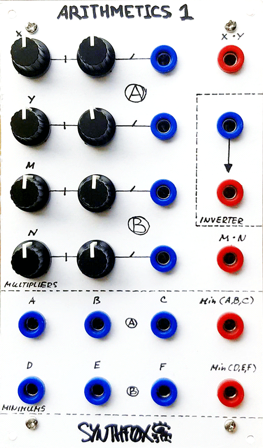
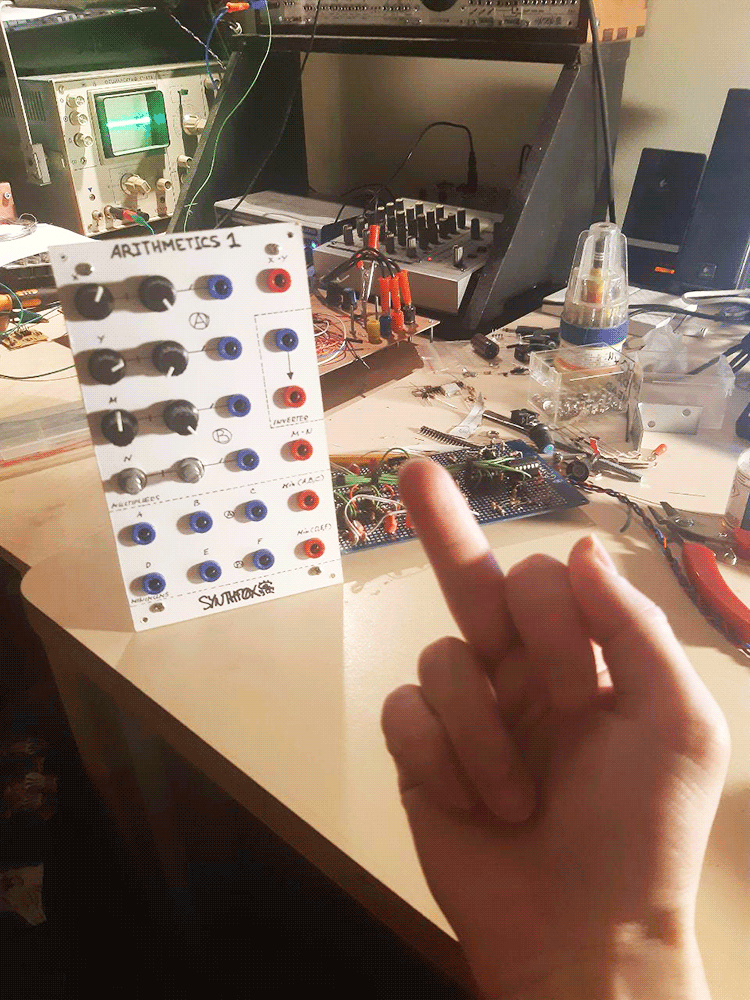
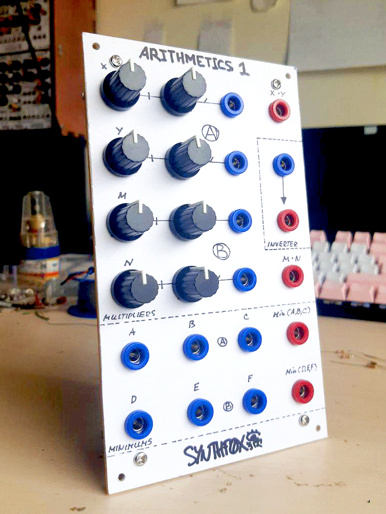
Following the VCOs, lags, clocks and stepped randoms, the concept FOXYSTEM-format box gets a grey horse of Arithmetics 1. On the lid, it's not as fascinating as, say, the Control Combomodule - however, it is an extremely versatile and important module that suits many needs.
The top part of the module is the voltage mulripliers section. Two identical units perform a multiplication of two DC signals (X*Y and M*N, respectively). Every input has an attenuator and an offset knob. A multiplier covers a wide range of uses. The most obvious are: ring modulation style sound out of two VCOs, a VCA that can also inverse the sound if needed, a voltage-controlled attenuator for CVs (same as last thing, but somehow, people don't use VCAs for anything but sound), as well as a frequency doubler made by multiplying the wave on itself. The creative usage of a voltage multiplier go far beyound these few, though.
Between the multipliers is a simple, in-and-out voltage inverter. It will output the copy of the input signal, inverted around 0v.
The bottom of the module has two identical minimum voltage selectors. This circuit looks at each input, and then outputs the one that's currently the lowest in voltage. If an input is unused, it will be ignored. The minimums can be used for creative CV chopping, 'crappy VCA' action, and even the logic 3-AND operation.
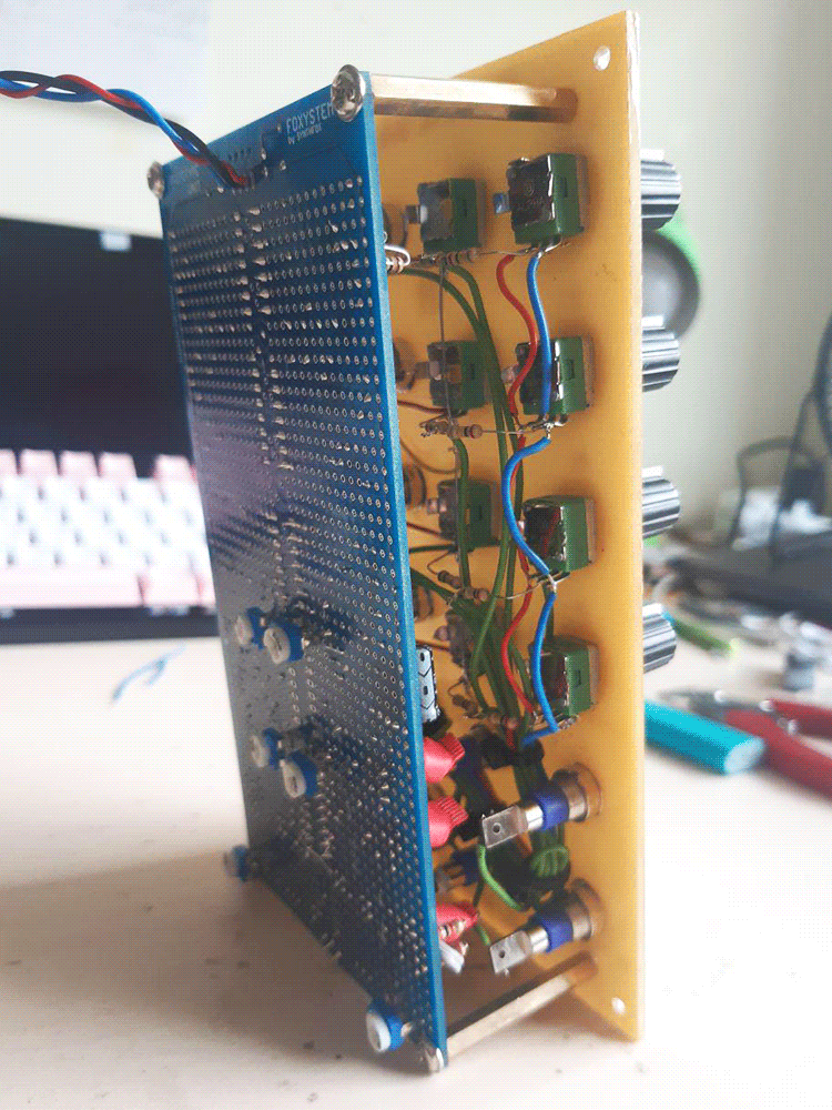
Both the multipliers and the minimums are discrete transistor core designs, and this brings drawbacks. Not only are these not the most precise devices in the world (precise enough to be musical, though), but also one would have to match 6 BJT pairs and 2 BJT triplets for this build, which is time-consuming. This eliminates the usage of complicated designs and expensive integrated circuits, though, and the result is a very versatile and ever-useful device!
Schematic
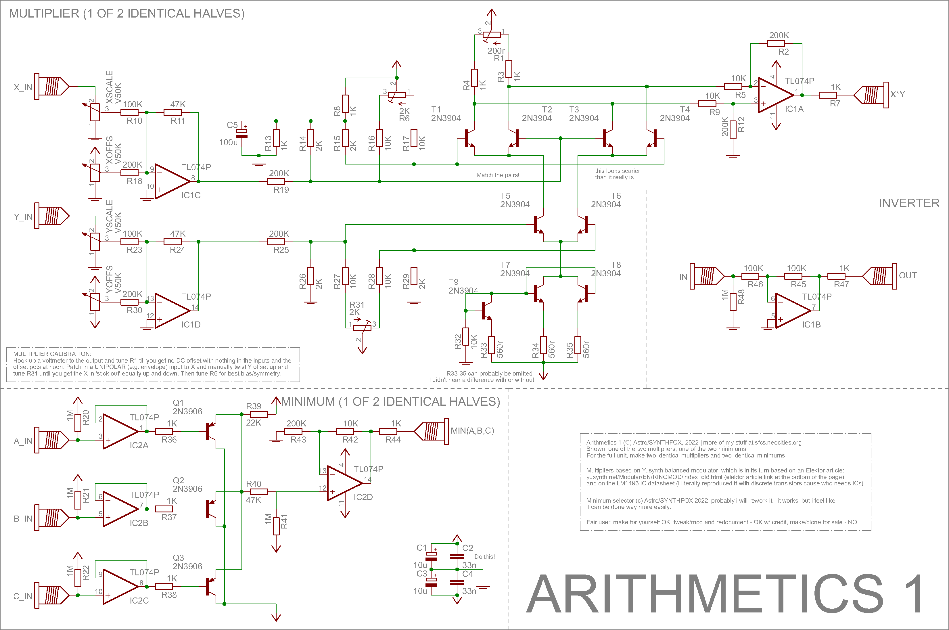
The multipliers part is a direct copy of my own Howard Multiplier design: the only things that changed is 2K resistors instead of all 1.8K ones (didn't change anything), both channels have bipolar offset knobs (easier to tune it this way), and the inverted output is eliminated in favor of a separate invertor submodule. Since otherwise the design is very much identical, and it is basically the same circuit, i suggest reading the original Howard Multiplier page for circuit notes.
Inverter is your old-and-usual unity-gain inverting op-amp. The only trick here is the 1M resistor to ground at the input; this prevents the input from floating and noising up the module when nothing is patched in. This inverter uses one of the four op-amps, other three are used for one multiplier. The other multiplier will also have a free op-amp: you can go ahead and be creative with it, if you wish, or - like me - be tired and just tie both of its inputs to ground to 'pacify' it (not shown in the circuit diagram).
The minimum selectors are what adds even more 'concept' to this concept module. I feel like these are a huge overkill and it could've been done way more easily. Every input has an op-amp voltage follower after it, with a 1M pullup resistor. If nothing is patched in, the op-amp will output 12v, therefore, never being the minimal voltage and not interfering with the action. Then, the three transistors form a kind of a... transistor-OR but inverse? It is hard to explain, but it makes sense to me. BJTs are strange. But it works. Then, there's a bit of a positive offset elimination and a re-amplification with the fourth of the four op-amps. This circuit has flaws. It won't faithfully reproduce waveforms that are rail to rail in amplitude: it starts clamping positive voltages at about 11.5 volts. It also has a slight (inaudable, but it should be there) nonlinearity at zero-crossing due to the 0.7v p-n junction minimal-voltage-difference-to-kick-it-off thingy. I have to experiment more with this setup: it feels like this kind of a thing can be done more easily. No, three diodes and a buffer are too simple.
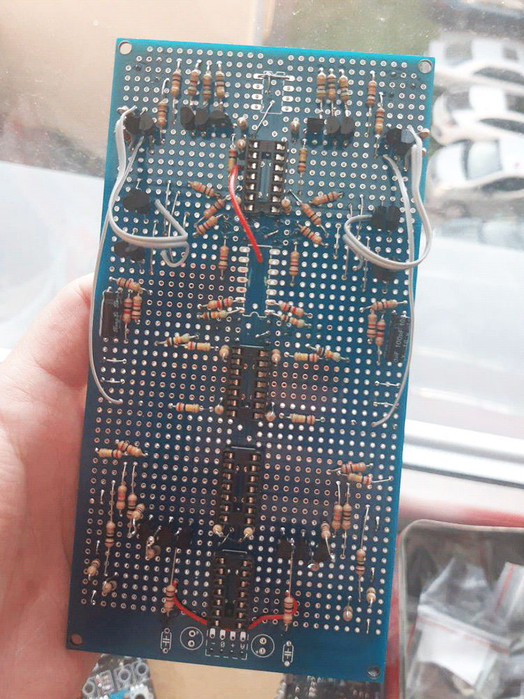
As one may notice, this build has a LOT of BJTs. For the multipliers, i strongly advise to match the pairs and triplets. If unmatched, the thing may have bad offsets and clicks here and there. For the minimums, i didn't bother matching the transistors, as it's not that critical in the design, and it works just fine. This means, you need 6 NPN matched pairs and 2 NPN matched triplets for the entire build.
CALIBRATION:
- if you have no scope, or only bipolar signals (like a VCO), or want to try a different method - check the original Howard Multiplier page for a different, ear-and-multimeter approach.
- Set all attenuators full CCW, all offsets at noon. Hook up an oscilloscope to the output. Tune R1 until you get no DC offset (0v reading).
- Now put the output to your system out. If there's audable noise - tune R31 (and then R6 if nothing changes) until there's no noise.
- Put a unipolar signal, like a cycled envelope, to the X input. Change the Y offset up and down, tune R31 until the output gets equal amplification in positive and negative ways (it should 'stick out' equally far on offset full CW and full CCW).
- Disconnect the test signal, tune R6 for no DC offset. Alter between probing the system ground and the output - the voltage should be the same.
- Reconnect the test signal, mess around and find the best positions for R6 and R31: amplification should be equal to positive and negative side, and more or less same no matter which input the signal is put into (the channel you put the input to should have its offset at noon; you turn the other channel's offset up and down).
- Carefully drop a bit of nail polish to the edge of each trimpot to fix in in place. Done
Media
A multiplier acts as a VCA in a simple krell patch. The sound rejection at zero is near-perfect to my ear, although obviously inferior to a dedicated VCA circuit.
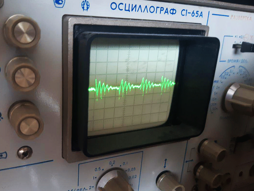
two VCO tri outputs multiplied, for a ringmod-style sound. Playing with offsets reveals some of the original oscillations aling with the ringmoddy sidebands. Best part: you could use a voltage summator and voltage-control this effect, unlike on the conventional ringmods.
a multiplier multiplies one bipolar lfo (saw) with a bit of a positive offset added by another (triangle) without offset, the output controls a VCO's pitch. The result is a sawtooth beating 'approaching' zero from above and then from below, in a cycle, crossing a moment when there's no modulation whatsoever.
a minimum processing three sawtooth waves, making it a kind of a drone-extracting mixer.
a minimum processing two low-frequency oscillations (saw and triangle) and some noise, then controlling a VCO with the resulting interesting patterning chopped CV.
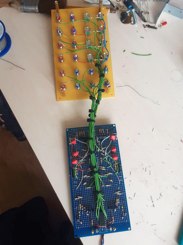
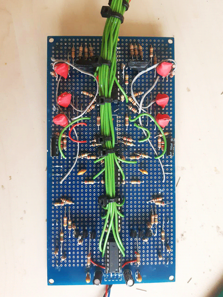
Pictures