About
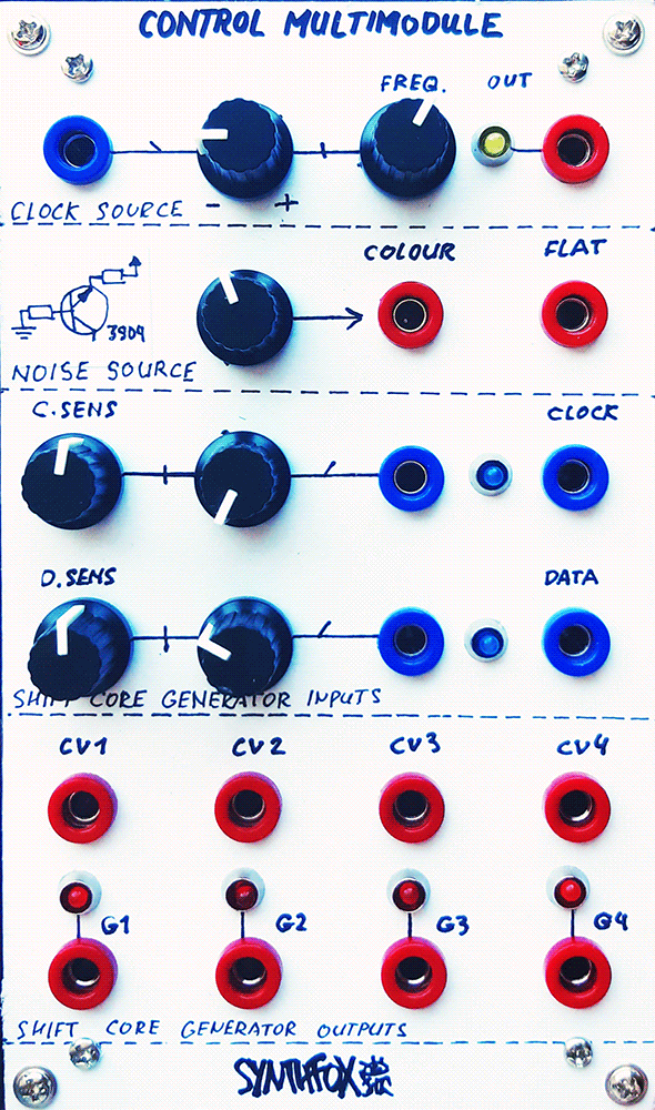
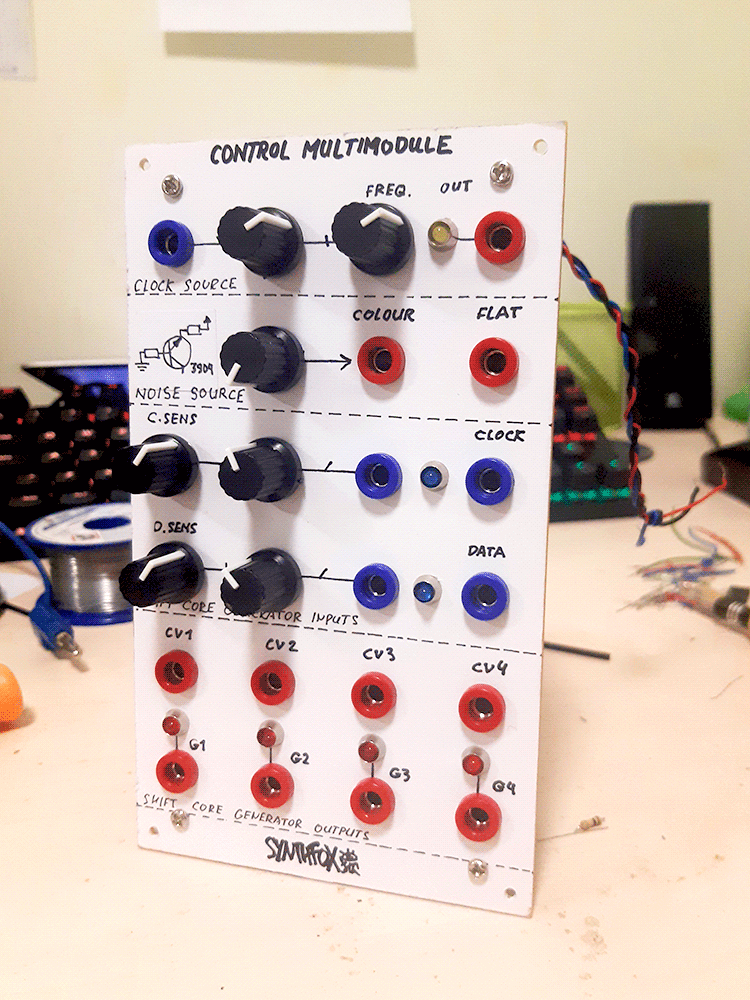
The Control Combomodule is a swiss knife module for, well, controlling things. At the top of the unit is an improved version of the SFP41 Enhanced Clock Source - a very wide range clocking squarewave pulse generator. It has the initial FREQ. knob, and the dedicated CV input+attenuverter. The output is indicated with a yellow LED. Below the clock source is the noise source - an alternative version of the one SFP42 Random Factory has. Instead of having dedicated tunable LP/HP outputs, it has one 'colour' output with a knob that fades it from rumbling low-pass to hissing high-pass sound; this output is useful as a pre-equalized audio source. The 'flat' output is more CV-usable, high-amplitude, low-offset, constant, and more or less flatly distributed noise. Below the noise source is the Shift Core Generator - also part of the Random Factory, and prior to that - the Shift Core Generator module itself. Like on the Random Factory, there is a clock and data inputs, each with a dedicated threshold knob and attenuated threshold CV inputs (mislabelled 'sens.', or sensitivity, on the panel). These controls determine, starting from which point the voltage at the respective input (clock/data) is treated as a logic 1, and under which it's considered a 0. The comparison results are indicated by the blue LEDs next to respective inputs.
On each rising edge of the clock, the CD4015 binary 8-bit shift register throws out the last bit and shifts its contents by 1 bit. Whatever was on the data input - 0 or 1 - is written into to the first bit. The contents of the shift register, represented as voltages (12v for 1 and 0v for 0) coming out of the CD4015 pins, are then used to form CV outputs on the lower third of the panel. CV1 has 5 possible equally spaced voltage states. CV2, CV3, and CV4 can take 16, 32 and 64 states respectively. They are perceptionally unrelated, e.g. if one goes up, it is not guaranteed that all the rest go up, down, or stay the same, although they do share the same initial data (the 8 bits of the register), so they are, in fact, related. Finally, the gate outputs at the very bottom, indicated by red LEDs, are 0th, 1st, 3rd and 6th bits of the shift register for G1, G2, G3 and G4 respectively. They are selected to be spaced apart different number of bits each, making for a nice source material for more complicated gate progressions. They output unipolar 0-12v gates.
The most obvious use of the module is self-patching it: clock source out to SCG clock in, flat noise to SCG data in, and then you have random voltages and gates at the bottom of the thing. However, the three parts of the module can easily be used completely separately, with other modules. One thing to try out before others is putting two triangle LFOs as clock and data, and play with the thresholds. SCG then becomes a 'pattern extractor', with the pattern being controlled by the LFO frequency difference and the clock/data thresholds.
Schematic
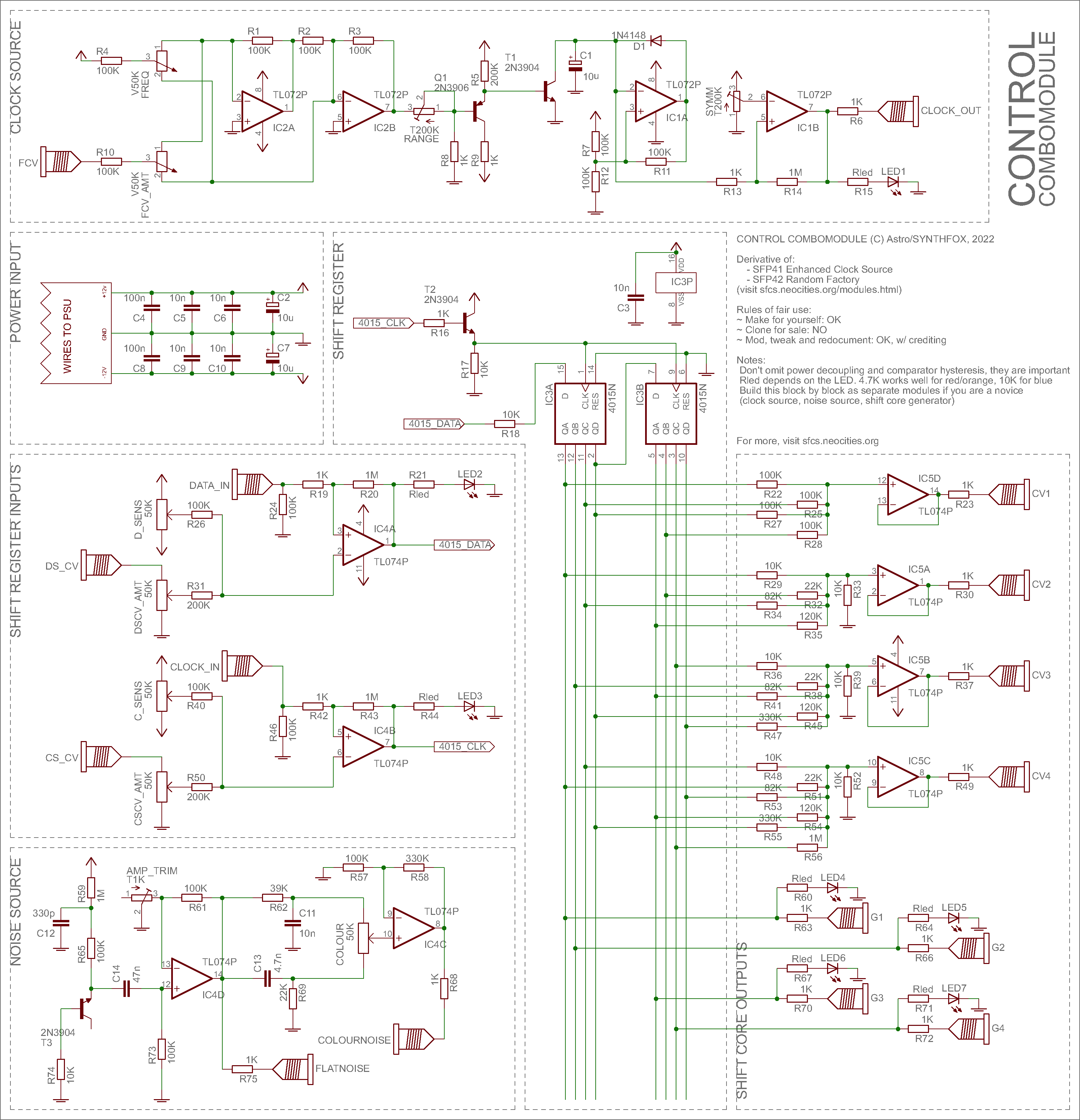
Since i already wrote up in-depth on how the preceeders of this module work, i will just leave links here and write some misc notes exclusive to this project.
- SFP41 Enhanced Clock Source (clock source submodule)
- SFP42 Random Factory (noise source and shift core generator submodules).
The clock source is almost a full copy, except for the range is now being tunable by the RANGE trmpot. The thing stops oscillating if you go too much to the high CV end, so make sure to tune the RANGE trimmer so that the clock oscillates reliably over the entire FREQ knob range. The CV input stage was also altered, with second CV in removed, and the first CV input pot now acting as an attenuverter. This is done by altering the summing stage (IC2A/B) to act as an attenuverting mixer. The clear schematic of such action can be found on the Doepfer DIY page. The capacitor switch has been thrown out, and the capacitor is 10u now, making the range go from very slow clocks to mid audio range. Increase to go slower, decrease to go higher.
For the noise source - it's a copy of the SFP42 one, except the DC decoupling capacitor C14 has been reduced from 100n to 47n for lower offset, and the filtering stage is now a blatant copy of my beloved Big Muff Pi tone stage, with a compensating amplifier IC4C.
The Shift Core Generator stage has been barely touched, but simplified a bit. The count of CV outs is reduced from 6 to 4, and the 5-state one now has a sad non-inverting repeater instead of the chad dual-inverting repeater with the cool virtual ground benefits. Still works just fine. The gate outputs are taken directly from the shift register instead of creatively XORing them, like in the Random Factory: i decided to roll back to the original Shift Core Generator gate output scheme for access to raw shift register contents and possibility to use them with, say, boolean logic modules, at will.
Media
Please, visit the SFP41 and SFP42 pages for demo recordings. This module does pretty much what those two do.
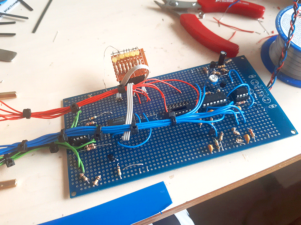
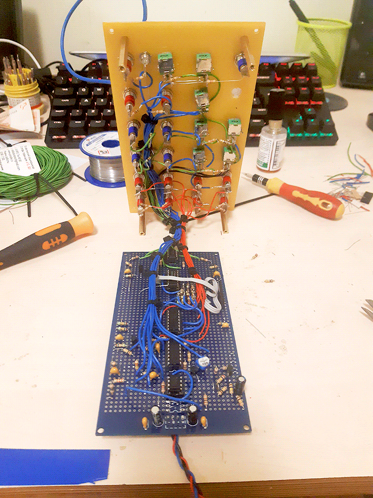
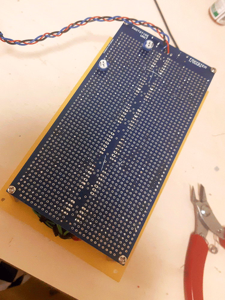
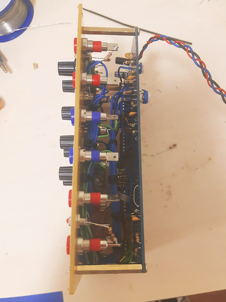
Pictures