About
Do you like maths? No, not the Make Noise Maths, the maths where you multiply and divide and stuff. Yes? Good, do you like to suffer while matching transistor pairs? Yes? Then this build is for you! The Howard Multiplier is a device for multiplying two signals, with its core made out of discrete transistors. Put in two signals X and Y - you get an X*Y and an inverted X*Y (or -X*Y) output. Extremely handy for a whole range of applications, starting with the boring VCA and ring modulator uses, and going all the way to controlling one CV's amplitude with another, dynamically attenuverting things, using it in feedback loops for interesting effects and so on - all of this with a simple voltage multiplication function.
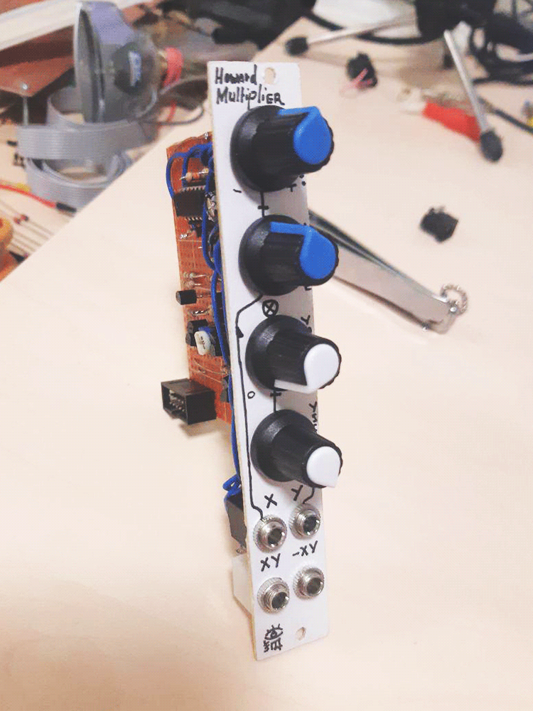
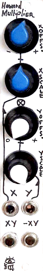
The module has two inputs - X and Y. Both have dedicated attenuverters and offset controls. The offset knob goes from 0 to 12 volts for X, -12 to 12 volts for the Y input. In my build, i confused the two channels, so you can see here on the panel the markings are opposite. X input is normalled to Y input, so if something is patched into X and nothing into Y, the inputs will share the same signal. This way, the module can morph between a VCA and a parabolic overtone waveshaper by multiplying the signal on itself. At the bottom are the two outputs: multiplication product and the inverted multiplication product. Of course, the product is 'fit' into the supply voltages' range after multiplying: you can't get 144 volts by slamming +12v to both X and Y; it will produce around 10 volts on the uninverted out and around 12 on the inverted one, meaning the inverted output is a bit better 'fit' into the range, while the uninverted one is a bit limited. This did not ever matter too much in practice for me, though.
This module requires four matched bipolar junction NPN transistor pairs (in fact, one of them even better be a matched triplet), and i used the matching procedure described by Ian Fritz (pdf in the 'download build resources' archive). It's quite simple to pull off and seems to be efficient: the build has minimal noise/bleed, although i used all resistors with 5% tolerance, single-turn trimpots and hand-matched transistor pairs of your usual 2n3904's.
For a considerably low part count and effort requirement, this module does an insanely good job and, in fact, multiplies. Possible build customizations for your consideration after using it for a bit: second attenuated input, AC/DC switch for one of the inputs, LED indicator, dual unit.
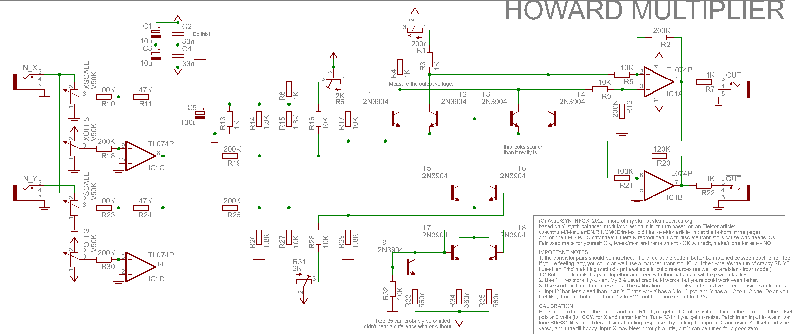
This unit is named Howard Multiplier because although it uses what people call a Gilbert cell, in fact, Howard Jones invented the initial design and the idea, and Barrie Gilbert later betterized it. It is not an original design, although i put hours of finding correct nominals for the resistors and modifying the circuit for better usage using falstad simulator - the schematic .txt is also in the download build resources archive. The design is based on Yusynth balanced modulator, which in its turn is almost purely a copy of an Elektor article design [pdf]. Both designs use an LM1496 ready-made Gilbert Cell IC - it's very expensive nowadays, so i used its datahseet to reproduce the insides of it with common discrete transistors and avoid rare expensive parts.
Schematic
Ok, Gilbert cell... here is a thorough explanation of how exactly it works, with numbers and stuff. I am not really good with this, so i will leave an actual explanation to the circuitry gurus (also lots of great vids on youtube), and just say that this is basically your usual 'differential pair VCA' design, multiplied. Pun intended. It's the same principle copied over itself so that.. one input controls how much the other one 'differenciates' the output op-amp? Really, go read up on this, cause although i did my research on this, i can't explain it better than those people.
Apart from the gilbert cell principle, there's a lot to say about this circuit, so let's begin from left to right. There are the inputs, X and Y. IC1C and D are set up as inverting summators, and as you can see, the feedback resistors are 47K, although the inputs are passed through 100K and offsets through 200K resistors. This is to cut the input in half (and the offset in four) in order to better fit into the linear region of the gilbert cell. If the amplitude after the summators is too wide, the signal will get slightly 'bent', which is not sonically interesting, but is also not mathematically nice, since we want out multiplier to multiply linearly, like in a textbook. Both of these summators don't have an un-inverting stage, as you usually would expect: i exploit maths to cut down on op-amps. Since both IC1C inverts X and IC1D inverts Y, the multiplication won't change: x*y = -x*-y.
After this, the X and Y enter the Resistor Hell through 200K resistors (to have the amplitudes at the cell even tinier - otherwise, again, distortion) , and then go to the gilbert cell. I replaced almost all values from the Yusynth/Elektor schematic because i stick to the few nominals i have on hand, but couldn't do without 1.8K resistors: i believe they can be changed to 2K by stacking two 1K's in series without changing the operation notably. I used 5% tolerance resistors throughout the circuit, so i believe that if you use 1%, you will get less bleeding than i did, although i managed to tune it to barely any bleedthrough. The trimm resistors should be multiturn - except if you're feeling adventurous. I used single-turns and had a lot of 'fun' calibrating the circuit almost by blowing on them, so, solid multiturn blue boxies are definitely much better here.
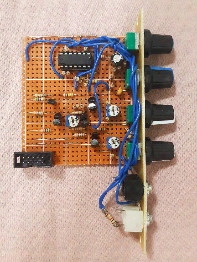
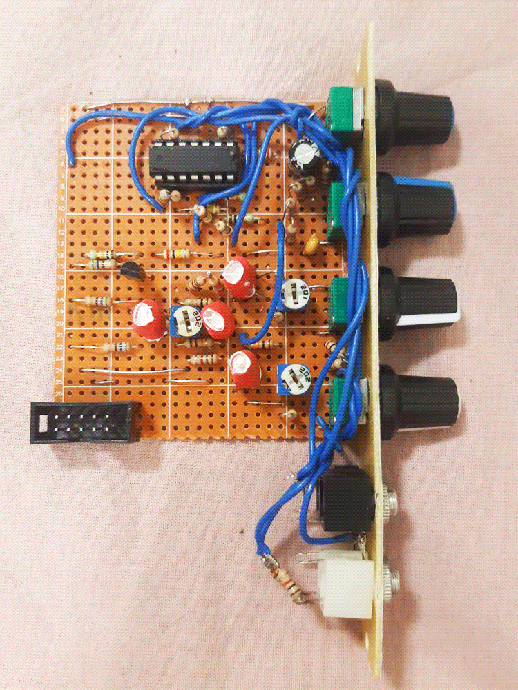
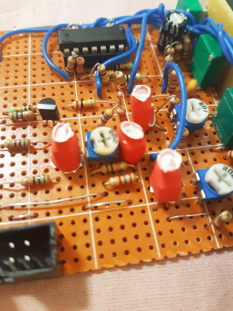
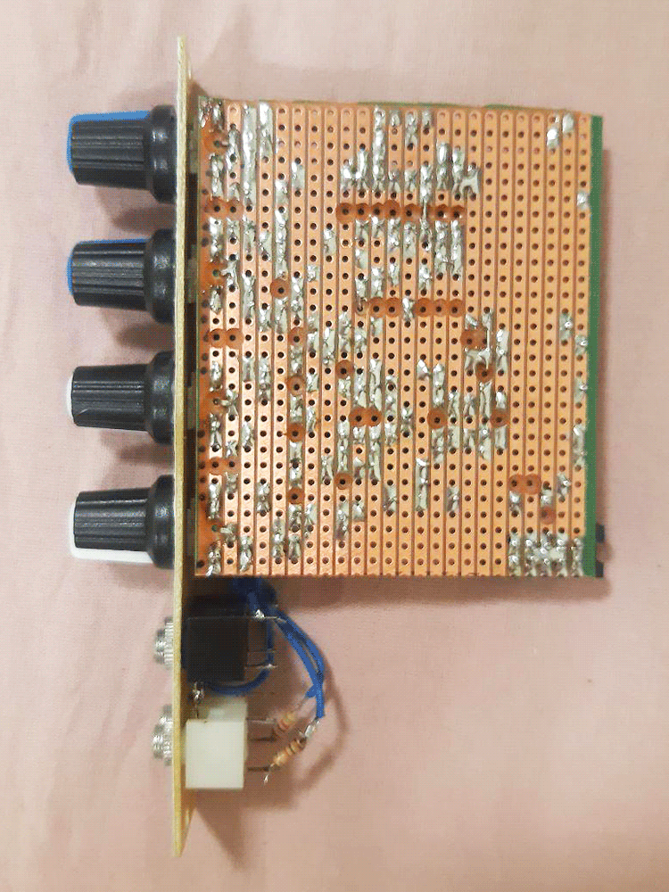
The gilbert cell itself is made out of three transistor pairs (T1/2, T3/4, T5/6) and one transistor triplet (T7/8/9). I matched the pairs using the Ian Fritz method and a crappy multimeter: probably if you get a matched couple IC or better tools than i do, you can get better operation, too. As for the 'triplet', i think it would be nice to have them all matched, but i only matched T7/8 and picked T9 randomly; works for me. Pay extra attention to what signal goes where here - this whole transistor clusterheck does not take a lot of space on the board, but it's easy to get lost if you don't check what exactly you are connecting where on each step. I soldered the transistor couples as close to each other as possible, then sticked heatshrink tubing pieces on them and, after heating it up with a lighter, injected some thermal paste into them for better thermal contact (see photos way below).
IC1A decodes the differential signal between the two junctions (R4/T1/T3 collectors and R5/T2/T4 collectors) into a usual signal and amplifies it to compensate for all the quietening we did to stay linear in the cell. Futher down is IC1B amplifying the signal by about 1.2 to get the fullest range possible, as IC1A's output is capped at about +-10v. If somehow you're getting inverted product on non-inverted out and vice versa - either just swap the outputs places, or swap the right legs of the resistors R5 and R9 places, so the difference at IC1A terminals is now opposite.
CALIBRATION:
- Set all attenuators and channels X offset fully CCW, channel Y offset at noon. Hook up a voltmeter (or multimeter) to either of the outputs. Tune R1 until you get no DC offset (0v reading) on your voltmeter.
- Now put the output to your system out. If there's audable noise - tune R31 (and then R6 if nothing changes) until there's no noise.
- Put an audio signal, like a triangle wave, to the X input. Nothing to the Y input to have its copy out there. Raise the Y input attenuator full CW. You should get a sound at the output - tune R31 and R6 so that there's no sound. Raising X offset clockwise should now increase the volume of your opened Y channel.
- Now do the opposite. Close the Y input attenuator and fully open X, drop the X offset full CCW, try playing with the Y offset knob. There should be a point somewhere around noon where there's almost no signal from X passing. Tune R31 and R6 just a bit at that point so that the bleeing is even less audable.
- Return to step 3 and check if you still have silence at X offset full CCW. If not - retune. Keep looping steps 3 and 4 until you get a combination of r31 and r6 where you get nice silence in step 3 and almost no bleeing in step 4. There should be a scientific method of doing this, but i'm no scientist.
Media
Your usual ring modulator sound. Multiplying the two triangle outs of the 40106 dual VCO. Playing with offsets and scales sort of works like a dry-wet control.
A lowpass VCF is processing an audio sawtooth. A slow cycling sawtooth LFO clocks a pitch sequencer and is also passed through the multiplier to control the VCF. Another LFO is used as the second multiplier input. It makes the result fade from inverted to uninverted version of the sawtooth LFO and back. As i mess with the 'modulating' LFO speed, the effect becomes different.
Morphing between a VCA and a strange frequency doubler/overtone generator by using the same signal for X and Y and playing with offsets
Pictures