About
Lyssa Wavefolder is intended to be a VCO enhancing unit. It creates waves of varying complexity, with strange overtones, out of a simple triangle or sawtooth (or any other continuous waveshape). Its usage is, of course, not limited to VCOs - it can process any sound signal and add overtones to it, or - since it's DC coupled - even process a CV signal to transform it into a much more complex motion. The three switches allow to adjust the action of this unit from mild wavefolding to insane overtone wilderness, and inbetween!
The design is based on the Alisa 1377 soviet synthesizer's "гармоники" (harmonics) section. Alisa is an underexplored gem, overshadowed by Polivoks both in post-USSR countries and abroad, and so many people don't know that this is a rare soviet synthesizer with a wavefolder. The strange part is while most batch-produced Soviet synths are, to one extent or another, clones of Moog and other synths "from the outside", Alisa - whose filter is a Moog ladder ripoff - has a unique wavefolder design that i haven't seen anywhere else so far. It uses the good ol' diode clipper as a base nonlinearity element - think Ken Stone wave multiplier and similar - but it uses two clippers per stage in a setup that i fail to analyse fully and completely. An even stranger thing is that although the knob that controls the wavefolder harmonics is essentially a voltage divider controlling a crude VCA, they didn't add any modulation to it - not even an LFO! So, i took it upon myself to figure out how to reproduce, enhance and modular-ize the design.
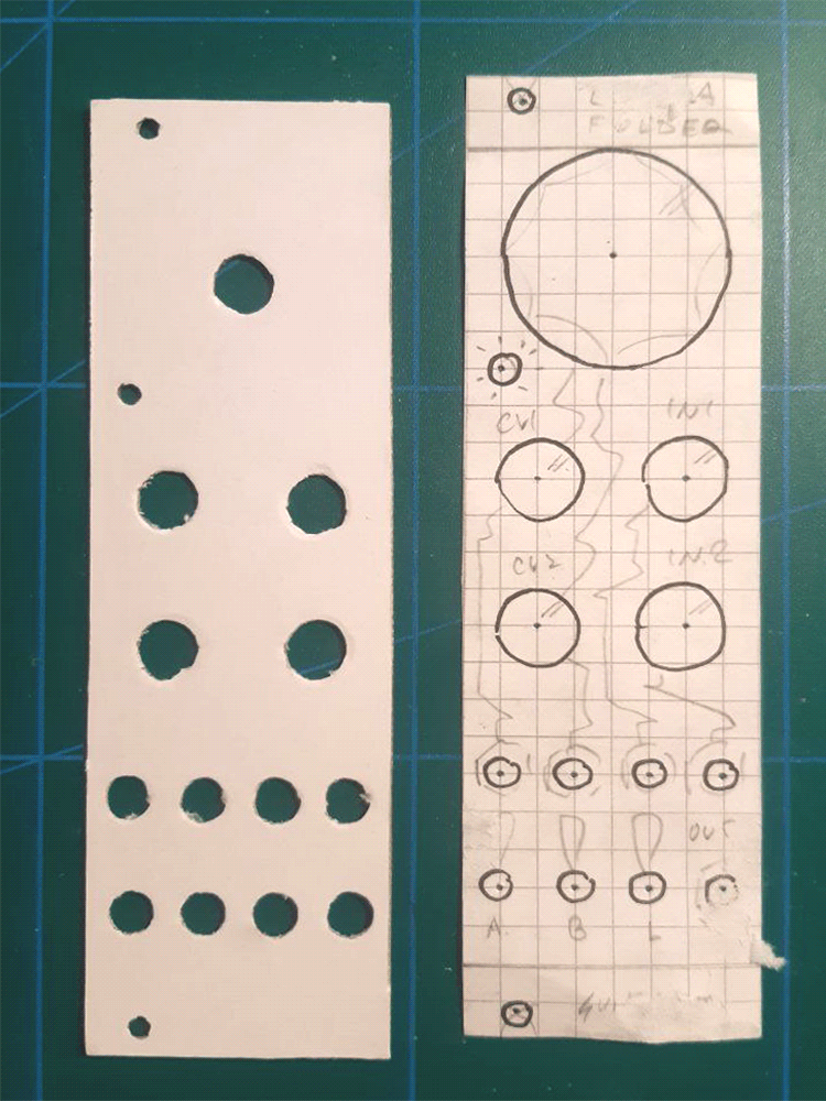
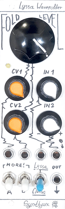
The unit features the big initial fold level setting, two CV inputs and two signal inputs - all fit with attenuators, and the output. When the initial setting is full counterclockwise an no positive CV is present, the unit completely shuts off the incoming signals like a VCA. Signal in 1 and CV in 2 are capable of amplifying their respective inputs by two, so, noon is original amplitude. In retrospect, i should've made CV 1 do that for symmetry reasons. Oh well! The builder should feel free to remedy that *wink wink*. Signal input 2 has an attenuverter instead of a mere attenuator, and its jack has a constant positive voltage normalled into it, hence if signal in 2 is unused, its attenuverter provides a positive/negative offset to the input mixture, causing serious alterations in the sound's character. The layout is, in essence, a classic in-cv-out configuration, with input and CV double up on, and the initial setting having a huge knob for the pleasure of usage.
The three switches at the bottom bring the unit beyound its original Alisa capabilities. When all three are off (down), the unit's action is similar to, although not precisely the same as, the original Alisa harmonizer. The "MORE!" A/B switches increase the fold depth of the first and second wavefolding stage respectively. This makes the unit more raspy and a bit more metallic in two distinct ways, sometimes adding a bit of clipping distortion to the signal. Hence, four stage depth combinations are possible. The "Classic/Lyssa" switch removes (classic) or adds (lyssa) a third wavefolding stage to the chain - not part of the original design - which brings a whole new dimension of metallicity and overtone buzziness to the sound.
This unit is a very capable wavefolder, packing a solid punch for its relatively low part count and small size. The switches basically give you 8 different wavefolder characters in one unit, which is quite awesome, too. The unit honours Wavefolder Pro, which it supercedes, by following its colour scheme. I wasn't very happy with Wavefolder Pro, so i won't be keeping it in my rack - but a bit of it will go on in form of layout and colour choices.
Schematic
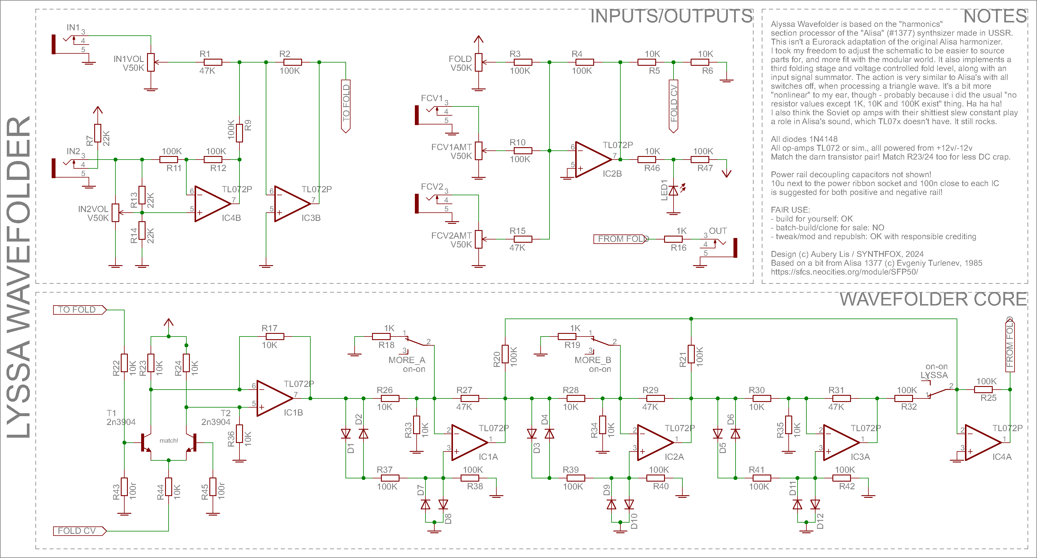
Fair notice again, just in case - this schematic is based on the Alisa 1377's harmonizer section design. Alisa was developed by Evgeniy Turlenev and associates in 1985, and the original design credits go to them.
Analyzing the original design a bit, we can see a familiar structure right at the beginning of the wavefolder section: a long tail pair VCA! I made a couple of those, so i know that it's possible to implement voltage control for the folding level easily. After detangling the original schematic further, we can see that there are two wavefolding sections, meaning we can add more. With this knowledge begins my actual design process.
First things first, inputs. The LTP VCA wants a negative voltage, the negative-r the louder, which is good - a single op-amp as an inverting summator (IC2B) will do the job. The indicator LED is reversed (because the CV is negative) and offset a bit with R47 so that its light curve is nicer. For the audio inputs, IC3B is set up as another inverting summator, and IC4B is a precision attenuverter, kassutronics style. I decided to implement an attenuverter for the audio input, as to be able to invert one input while keeping the other the same polarity, which yields a different resulting sound. One could easily repurpose that spare op-amp for something else, e.g. CV attenuverter, or a fourth folding stage. I don't bother un-inverting the signal after IC3B; since the original design is non-inverting and has no output buffer, i just used an inverting output buffer (IC4A) which will invert the signal back after it's done being wavefolded the hell out of. These two simple blocks, plus the output impedance, take care of the interface to the module
The wavefolding core takes after the original in shape, but not in content. The topology is preserved, but the values are, well... i did my usual "no values except my favourite five exist" thing and approximated it as much as i could. To be honest, the only thing that changed is that the resulting waveshape is a bit more curvy than the original, which tends to preserve a bit more of the triangle's triangleness; the difference is not serious enough for me to bother about it. The first thing in the wavefolder core is the LTP VCA around IC1B. I already made an LTP VCA module - you can read more about it here. The key point is, we divide the signal through R22/R43 to avoid distortion and stay in transistors' linear regions. The long tail pair amplifier is fed current through R44, and the maximal voltage difference between the two transistor collector - 10K resistor junctions is proportional to the current. No current - no difference possible, big current - big difference headroom, so, more current - more volume. Decoding the differential voltage to usual single-wire form over IC1B means we now have a current-controlled amplifier, and the "current" part is handled by IC2B, processing the CVs and pumping a proportional current through R44. The big difference from a usual LTP VCA is that the gain setting resistors (R17, R36) are rather small, meaning that we don't exactly recover the signal to its previous gain after dividing it down pre-VCA. This is good in this particular case, as to get the most out of the wavefolding stages, the signal, too, has to be rather small.
The folding stage topology is a bit of a mystery to me. There's the classic non inverting in - diode pair - ground thing, but also the signal comes to the non inverting in through another diode pair, and divided down by two with the two 100K resistors. The same signal comes to the inverting pin through another voltage 2x10K voltage divider, and then amplified with negative feedback. It has to be noted that there's no virtual ground at the inverting in of the op amp, since the non-inverting one isn't grounded, but rather is fed the double-clipper wave mishmosh. Decreasing the lower part of the 2x10K divider (e.g. R33) gives a significant boost to the folding action by (i think) enlarging the difference between the two op-amp inputs, so i put the MORE switch that adds a 1K resistor to ground parallel to the 10K when actuated. Adding a third stage is a no-brainer; copy and paste. I didn't go for four stages, as it was really hard to tame the values into where it doesn't just make the signal into either a fuzzy mess or a squarewave; feel free to experiment. The two stages are then invert-mixed over IC4A. No un-inversion required, as the inputs were already inverted once over IC3B. Another switch adds the third stage into the mix.
The design takes just eight op-amps and a rather small count of passives with a limited set of values, in contrast to a lot of harder-to-implement design with much more amps, and many passives with values all over the place. For this part count, it provides one hell of a punch to the guts with how insane it can get, while being perfectly capable of the original smoother wavefolding action, too.
Media
Basic fold level sweep test with a triangle wave as sound source and DC offset at noon. Each new sweep is with a changed switch setting: all off, A, B, AB, lyssa, A+lyssa, B+lyssa, AB+lyssa
Same as above but with a (slightly uneven) sawtooth
Two oscillators, one constant and one sequenced, to inputs 1 and 2, "fighting" in the wavefolder and producing completely new unexpected overtones. Not your usual mixdown!
Processing a triangle LFO through the unit and controlling a VCO with the resulting slammed-up wave to get interesting beatings and motions out of it.
A more advanced patch using the wavefolded sawtooth LFO as the main modulation
A little sequenced patched with the wavefolder and Jelly VCF processing a VCO triangle
Three triangle oscillators summed into the wavefolder, CV'd by a simple LFO.
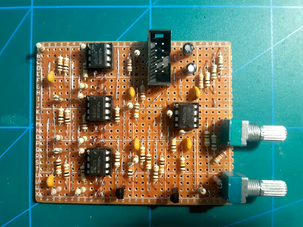
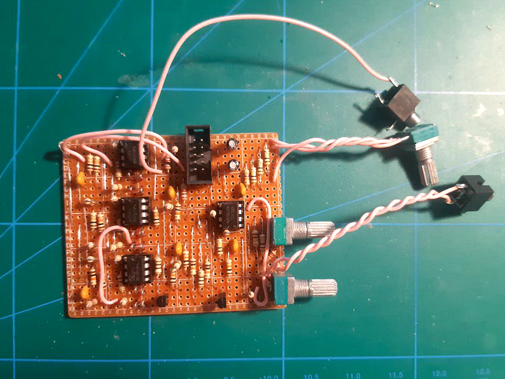
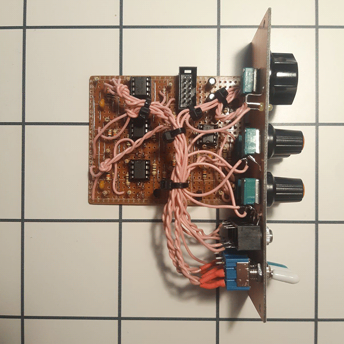
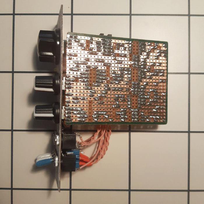
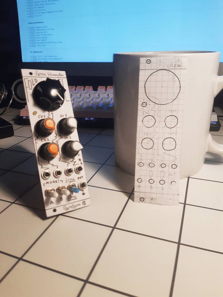
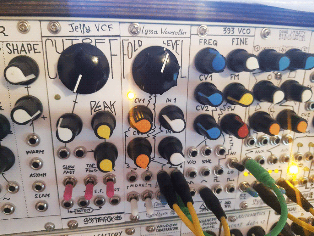
Pictures