About
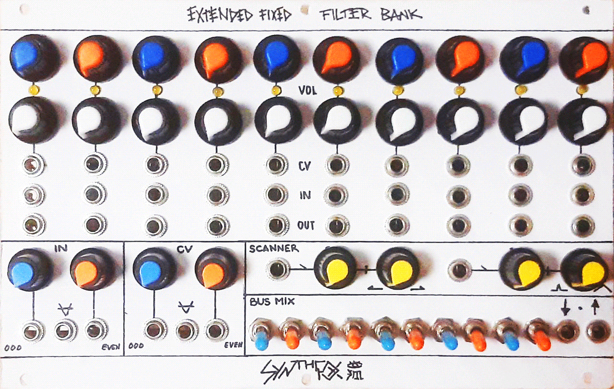
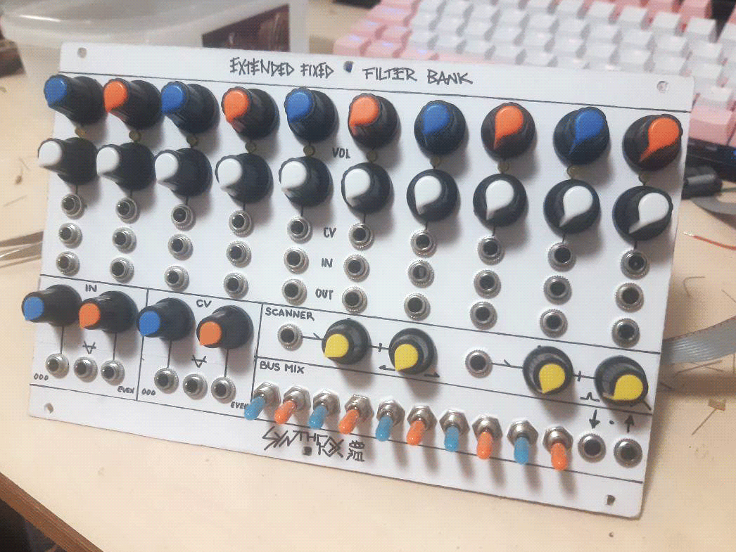
Stemming from Serge Resonant Equalizer and Buchla Model 296, the Extended Fixed Filter Bank contains a battery of 10 fixed filters with some associated individual and master controls. Each filter is a pretty narrow bandpass, which selects a tiny band portion from the incoming signal. Each of the 10 bands has such filter with sitting at its own unique center frequency and a VCA before the filter. Each has individual volume control, attenuated volume CV input, audio input and audio output. On its own, each band will just control the volume of the incoming audio with the VCA, then bandpass it, and output it.
While each band can be used separately, using them all together with the master controls and the mixing section is what makes the module so powerful. On the bottom left are the master inputs. Both the IN (audio) and CV (volume control voltage) sections have the ODD, EVEN and ALL inputs. the ODD and EVEN attenuated IN/CV are routed directly to odd number (blue) or even number (orange) bands respectively, and are added to the bands' individual audio IN and volume CV inputs. Odd and even does not refer to the frequency here, but just to the order of bands from left to right. The ODD and EVEN inputs allow sending the same audio or CV to a group of 5 bands - odd or even - simultaneously. Audio and CV sections alike, whatever is patched into the ODD input is normalled to the EVEN in of that section, meaning that the odd/even inputs can be treated as one "to all bands" input with "to odd" and "to even" attenuators instead, be the EVEN input not used. The ALL inputs, denoted with a mathematical "all" symbol, are normalled to the individual input jacks of all bands. So, ALL audio IN appears at every band's individual audio input, as long as nothing is plugged into it, and all CV in acts likewise with the individual CV inputs.
To the right of the master inputs are the scanner on top, and the bus mix below it. The scanner is a macro-control that allows to dynamically "scan" through bands: as the scan position knob is turned clockwise, each band fades in and out one after the other in order, left to right. The scanner width controls the size of the "scanning spike" (with the labels on the wrong sides - fixed later on): when fully clockwise, the scanner is very narrow, and as the scan position is moved left to right, each band fades in and out one after the other, with full silence inbetween, and without overlapping. As the scanner width increases (knob goes counterclockwise), each band's active area will widen up. At first, adjacent bands will overlap, and moving scan position no longer fades the bands in and out separately, but rather crossfade between them. As the width increases, the scanner will start grabbing more and more bands at once, so that as the position is moved, 2 or 3 bands are active at the same time. Finally, the widest possible scan spike covers almost all the bands at once. This tool presents insane capabilities of crazy inter-band morphing and animation. Disabling the scanner is easy: set it to narrow, so that the scanner doesn't reach the actual bands, and push its position to either fully CW or fully CCW to move it away from any band.
Finally, the bus mix section does what it says in the name: mixes down the bands into busses. Namely, two busses: the "up" and "down" ones. Each band's audio output is routed to an associated toggle switch, which has 3 positions. The band is excluded from either mixes if the switch is in the middle position. The up and down positions add the band to one of the two respective mixtures, available from the two jacks to the right. This can be used in many various ways in feedback and stereo patching, FX routing, and so on, and is also a handy live tool for excluding bands on the go without needing to patch anything.
The Extended Fixed Filter Bank is something i've been working on for a long time, and it is a tool of many uses and purposes. It sounds great, has a bit of a character to it - because SDIY - and is an amazing sound transformer. The only downside is that the build is extremely complicated, took a long time and drained my soul in the process. Be warned of this! It's a huge project, and you don't want to take on it if you don't have the time and the power for it.
EXPERIENCED BUILDERS ONLY! THIS IS A HORRIBLY BIG, DISPROPORTIONALLY COMPLICATED PROJECT! BUILD JUST ONE BAND OR JUST THE VCA IF YOU ARE A BEGINNER! THIS WILL HURT YOU IF YOU UNDERESTIMATE ITS COMPLEXITY LIKE I DID! THIS IS SOME REAL HARDCORE CRAP AND I'M NOT EVEN JOKING!!!!
Schematic
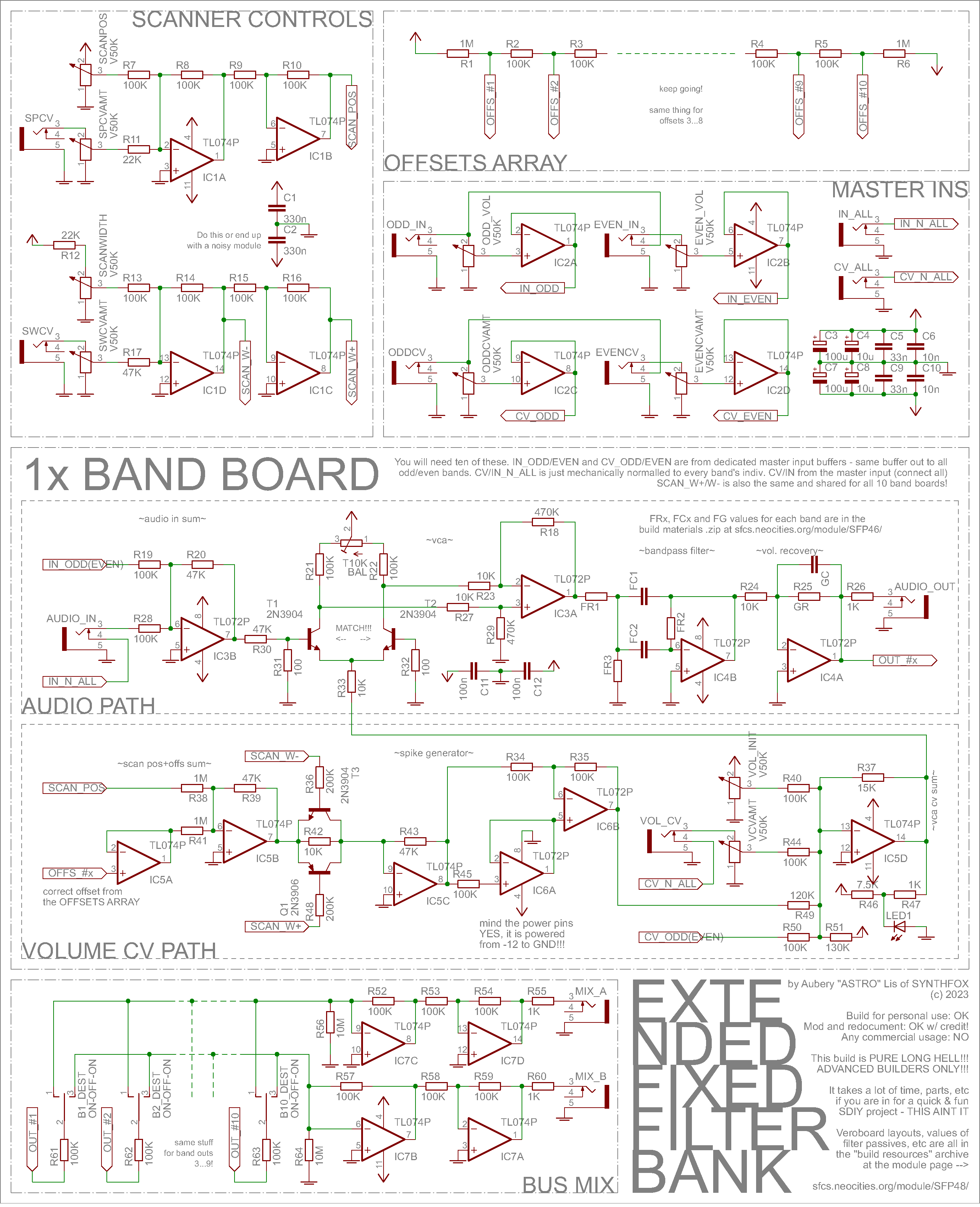
While the thing itself is complex, just because of its sheer size and effort i put into designing it, the schematic is quite simple. This note will begin with the band board overview, and then i will explain the master controls.
For the audio path, we have a classic long tail pair VCA, which is analogous to this other VCA that i did before - just stripped of its precision features, as i don't care much about slight DC offset or minor distortion. You can read on that page in-depth on the VCA design: long story short, IC3B invert-sums the master odd (or even) audio post-buffer an the individual input, R30/31 divide it to be very Smol so that T1/T2 (which, by the way, have to be a matched pair!) do the differential VCA magic with. Then, IC3A recovers the volume and decodes the differential voltage to ground-referenced voltage again. After the VCA, IC4A/B form a simple bandpass filter followed by a gain stage. The values of FR1/2/3 and FC1/2 directly impact the bandpass filter properties; the list of values i ended up using is in the "download build resources" zip archive at the page top along with some other info. GR sets the gain post-bandpass, as some bandpasses "feel" quieter than the others: a possible improvement is to replace it with a 200K trimpot and adjust all bands' gains when everything else is assembled and tested for perfect balance; mine are still a bit disbalanced if you listen closely. GC is a capacitor that turns the gain stage into a lowpass filter, which is applicable to bands 1 through 5. This is because this bandpass design somehow sucks at the highpass part a lot in low frequencies, so additional lowpassing is needed to satisty the audial perception. These were selected by ear. The audio is output to the individual out jack through 1K output impedance, and also is routed to its corresponding switch on the bus mix.
The CV path is a bit trickier, but is not too complex either. Its task is to derive the resulting CV that will drive the VCA in the sound path. This CV is the inverse-sum of the initial volume setting, attnuated CV input (to which ALL CV input is normalled), ODD or EVEN master CV input, and the "spike generator" output. The VCA is driven by negative voltage, the negativer the louder. The only tricky part is the spike generator - this is what makes the scanning possible. It turns the scanning position (voltage from -12 to +12) into a spike that stays at 0, until the (global) scan position reaches a particular voltage set by the OFFS_#X voltage, which for now we will assume zero. As it nears this offset voltage, the spike output rises. As the scan position goes past and away from the OFFS_#, the spike output decreases. This way, the band fades in and out as the scan pos knob is turned. The width of this "hill" of rising and falling is controlled by the scan width control. This basically means taking an inverse modulo of the scan positioN: -12..0..+12 saw -> -12..0..-12 triangle, if the knob is being turned from full CCW to full CW. This is done by IC6A/B that form a neat (more or less) precise inverse modulo device handy. The trick is to power IC6 from -12/0 instead of -12/+12 for V-/V+ respectively: IC6A is a voltage repeater and it will repeat the negative portion of the scan position signal just fine, and will stick to near-0 for the positive half. This makes IC6B behave as a repeater for the negative part of incoming scan pos, and as an inverter for the positive part, essentially creating our inverse-modulo triangle. Since it is offset to -12V and we want it to sit at 0 or so when the scan position is far from the "hill", R51 compensates that with a positive offset, driving the overall sum to about 0. R47 drives the band's indicator LED, while R46 provides sufficient offset for the LED to go off smoothly along with the band's actual CV. The value of 7.5K was chosen by eye to work best with a 3mm yellow matte LED: you do your own testing!
But now the question: how do we squish this hill, in order to control its width, and the space each band takes on the scan position knob rotation? The answer is IC5A/B/C and T3/Q1, which form a really terrible VCA that goes from 1 to definitely more than x25. It has been made by fricking around with circuits and i don't have a sane explanation of how it works. But what it does practically is, it amplifies the incoming scan position signal, meaning the resulting modulo spike becomes narrower as the amplification rises. The amplification is controlled by a positive and a negative copy of the scan width control, sent to the bases of Q1 and T3 respectively. In my understanding, it just lowers the overall resistance from IC5B out to IC5C inverting input, resulting in a larger overall amplification at IC1C.
This takes care of squishing and stretching the hill, but if we assume that OFFS_# is 0 for all bands, their "hills" will start, peak and end at exactly the same places! For this reason, OFFS_# is individual for each band, and is derived from a voltage-dividing string of R1...R6 denoted on top right - but it is 11 resistors in practice. This string generates a bunch of offset voltages, equally spreaded from around -8 to around +8 volts. Each band gets its own unique offset, low to high for low to high center frequency. It is buffered with IC5A at each band, and then summed with the global scan position. This results in each band's own local scan position (post IC5B) being offset from one another in equal voltage distance. In other words, every band's "hill" is now moved, and their peaks are distributed equally over the course of the scan position knob. This way, we can now turn the scan position knob, and each band will fade in and out, one after the other, as the knob goes from CCW to CW. The wider the scanner is, the more the "hills" will overlap, since they each take more space, but don't move anywhere from their positions on the scan pos knob. This allows to use the scan width control to morph from scanning individual bands, to crossfading between two adjacent bands, to fading between triplets (and other -plets) of bands, up to brushing the entire bunch of bands in one go.
Finally, the master controls. Quite simple. On the top left are the scan width and position, both derived from Ye Olde bi-inverting op amp summator. Scan position only uses the non-inverted (or rather doubly inverted) output, while the width control needs the inverted 0...-12 and uninverted 0...+12 versions from IC1D/C respectively to drive the occult crap transistor "VCA"s. The divider string on the right has already been discussed above: i ran it directly from board to board at the back of the unit instead of routing 10 additional connections. Finally, the master inputs are merely attnuators for the actual inputs, with op-amp voltage repeaters following them to easily deliver the audio/CV to the odd (or even) bands. The ALL IN/CV inputs are simply wired to be mechanically normalled to every band's individual IN and CV input jacks: no buffering or anything is going on here, although it probably wouldn't be a bad idea to buffer this. Works for me though!
At the very bottom of the schematic is the bus mixer. It uses the same bi-inverting summation as the scan pos/width summators do - nothing special here. No DC decoupling caps for audio are used, as after the bandpass filter the audio will surely be decoupled of any major DC offset possibly induced by the VCA bit of the audio path. 10M pulldowns ensure stable zero if no band is switch to a particular bus. Since the bands each cover a different tiny bit of audio spectrum, mixing them at full volume causes no clipping in most cases. That's all there is to the bus mix section.
This design is not that complicated at all, really, and no magic is going on. Except for the spike scan pos VCA thing - i'm pretty uncertain what exactly does it do, so, magic, i guess. The tough part of this project is practical implementation of 10 such boards + main control boards, all wrapped into one package and wired together. I am sharing my files through the "download build materials" link at the page top, yet, one should be aware that those are imperfect, and the unit i ended up with will be a horrible trouble to maintain in case anything in it breaks. For this reason, i advise to not use my band board design directly, and instead approach it critically and design your own, better one. For instance: be sure to bring the trimpots to the back of the board so that you can tune them after you assemble the unit! Also, maybe do something better than what i did by using bare wire that skewers through all 10 boards to deliver power and global stuff like scan position/width etc - maybe use a pin header and a detachable ribbon cable bus with headers instead? This project is pure hell, a mess of wires, a pain in the ass, and if you take on it and finish it, i am eagerly waiting for photos and a fun story.
Media
A simple scanner sweep with white noise to the ALL audio input. No external CVs, all bands' volumes full CCW. First sweep is with the narrowest scanner width, then wider, and widest.
Same as above, but with a phase modulated tone instead of noise.
A more musically interesting version of the patch above by sequencing the scanner width and position, and shaping the output sound with a synchronous decay envelope using a VCA module.
Basic feedback exploration
Feedback against an audio delay module
The bus mix section can be used for stereo effects, to creatively send particular bands to the left, right or none. Scan position is modulated by an LFO, ODD and EVEN CV inputs receive asynchronous LFOs too. White noise is fed to all bands through the ALL IN jack.
Filterbank based protofreestyle!
A very neat spikey noise patch using the scanner, sequenced by the random factory. A short decay envelope is patched to ODD CV input, and from there is distributed to both odd and even bands (since EVEN CV in is not used).
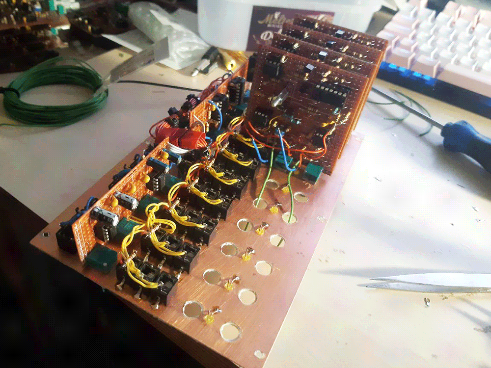
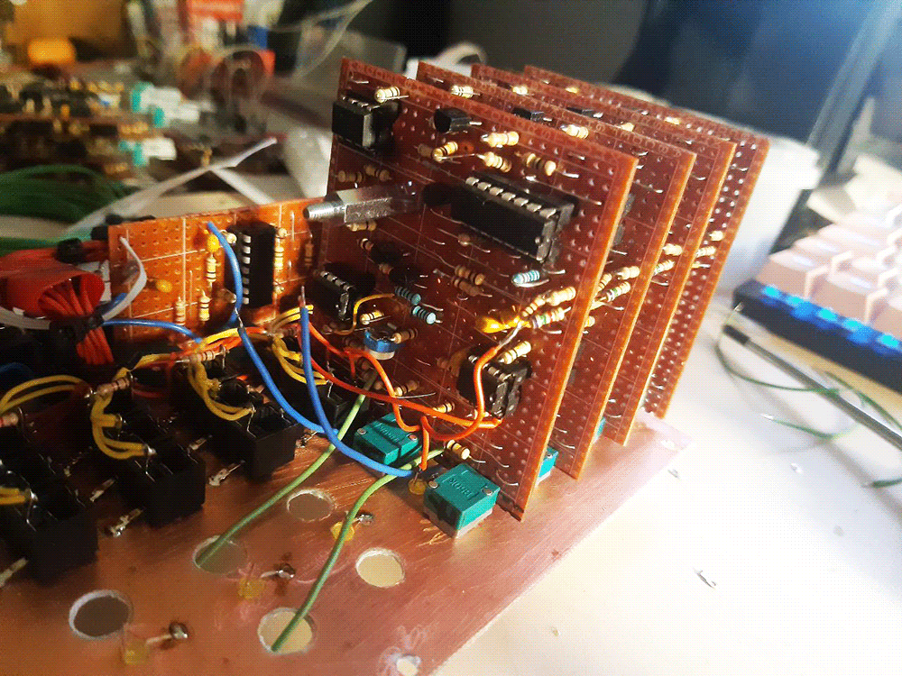
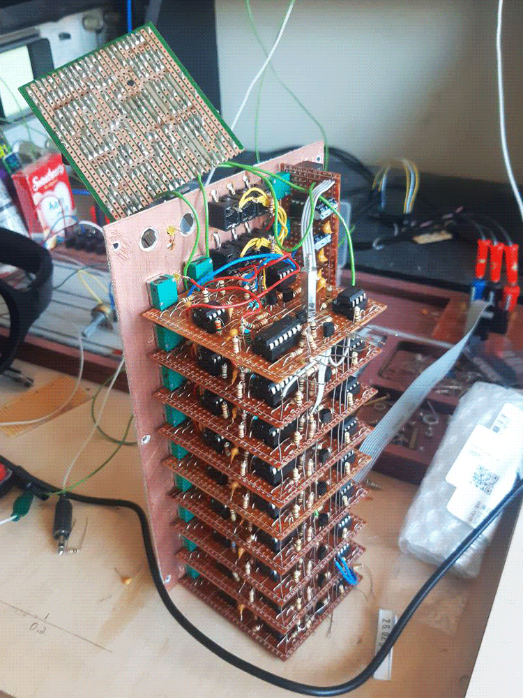
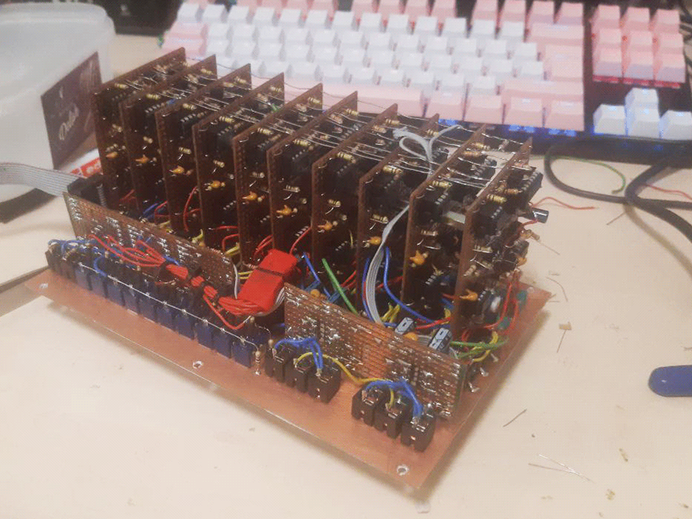
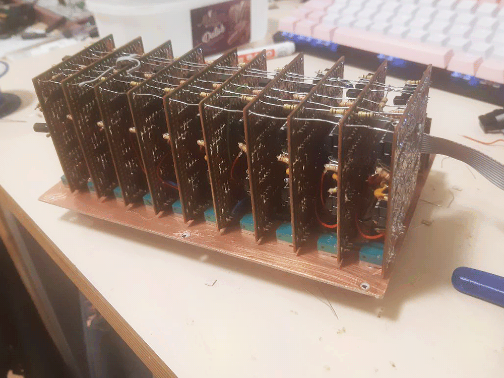
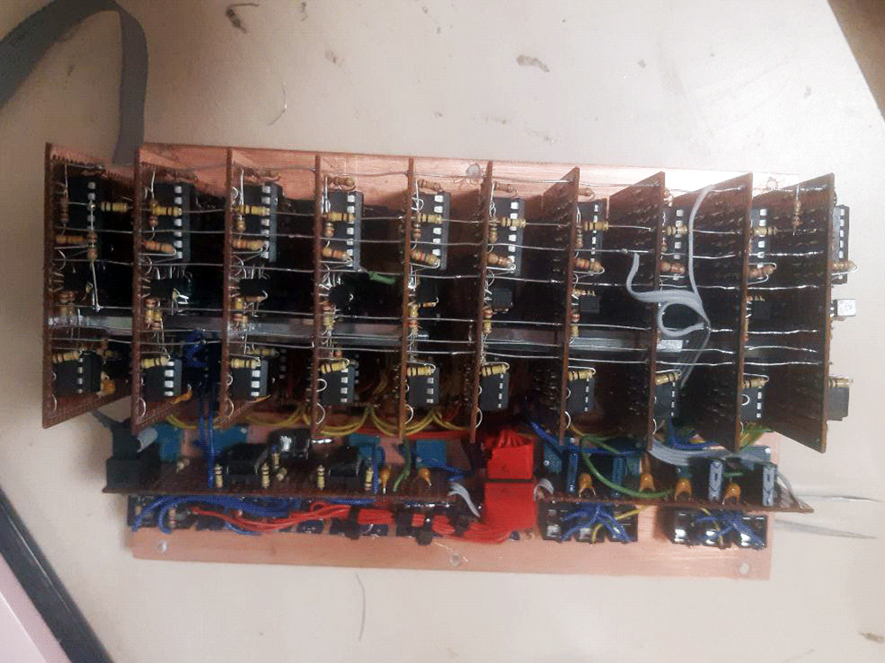
Pictures