About
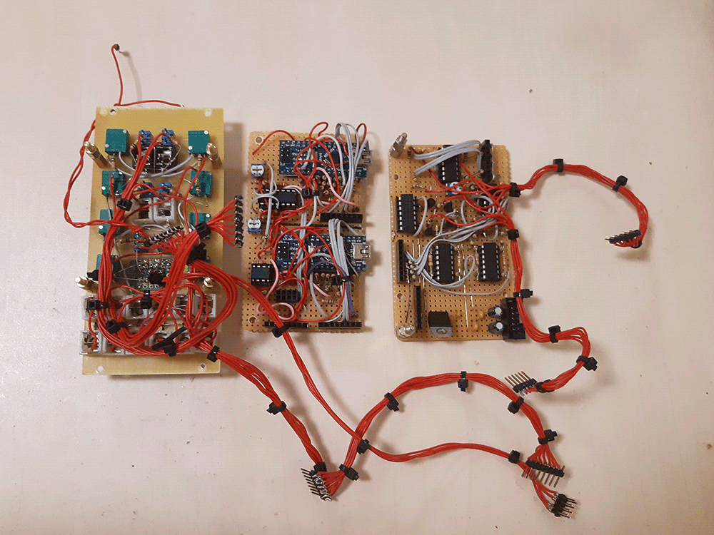
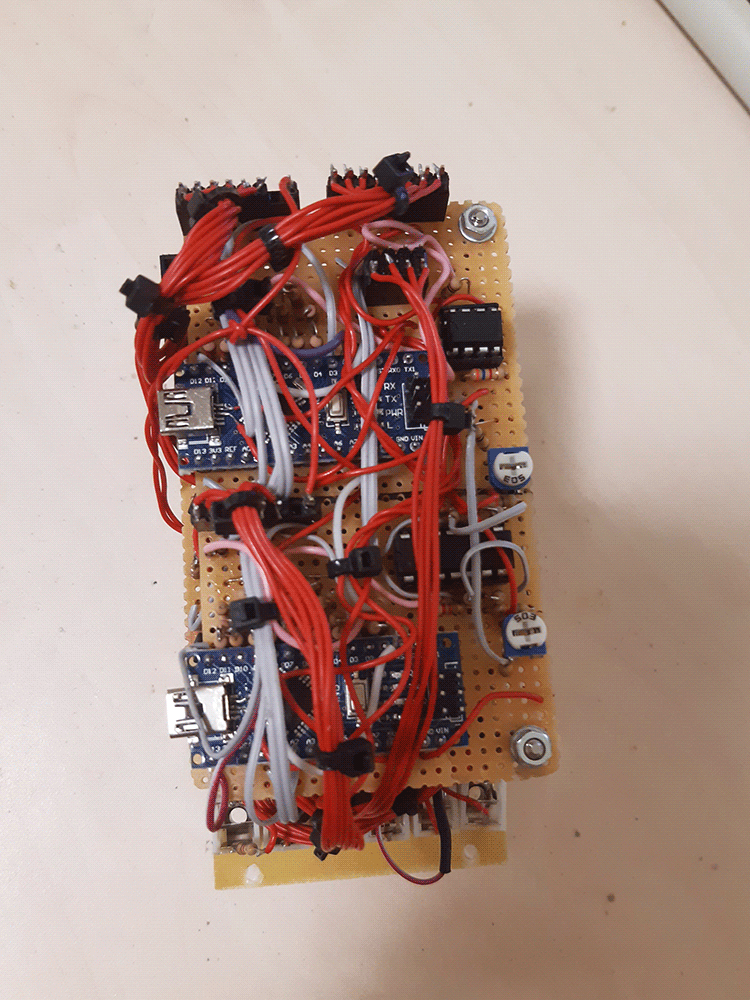
This one is a dual voltage-controlled sampler module. Both halves are identical and utilize an arduino nano as the digital processor and sample memory. It's heavily inspired by how the Linndrum works - i had no EEPROM memory programmer, so i decided to use the next closest thing, and just use an arduino as a memory block. And, since i'm using it anyways, i decided to enhance things a bit: each side has not one, but two separately triggerable samples, and two selectable effects (EFX). The level of effect can also be voltage controlled, and the effects vary from a crude digital VCA to a weird bitbanger distortion. Samples can be looped independently, too!
This is a hardcore build! It WILL require a lot of circuit debugging, it's complex, and it will spend your time and parts for nothing if you have no skill yet. If you know what you're doing, i triple dare you to build one, but otherwise - aim for something simpler first!
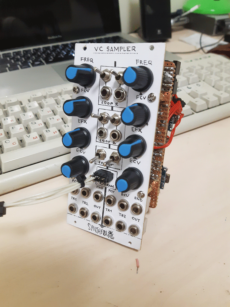
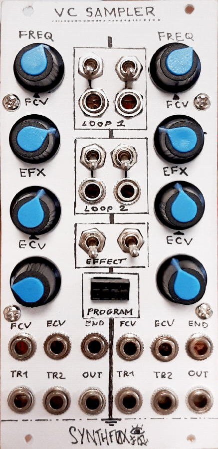
Each side has a frequency control - it determines the speed sample will be played at - and a CV input/attenuator for it. Also there's an EFX level knob, and a CV/attenuator for it, too. Two trigger inputs are for two different samples: they're slow and non-rectangular signal friendly (have comparators behind them). The OUT output is the actual sound: glorious 8 bits of sheer quality sound from an R2R DAC, COVOX-style! The END output emits a gate every time the sample reaches its end. There's also a bunch of toggle switches: you can select if the sample should be looped or not, and an external gate (no comparator this time) can inverse your selection. This setting is individual for each of the two samples in a sampler (e.g. you can set one to loop, but the other to just end). Finally, the effect toggle switch selects between the two """DSP""" effects.
While the hardware part is laid out here, it, the Arduino Nano firmware and the python utility is included in the .zip archive - you can get it by clicking 'download build resources' at the top of the page.
Schematic
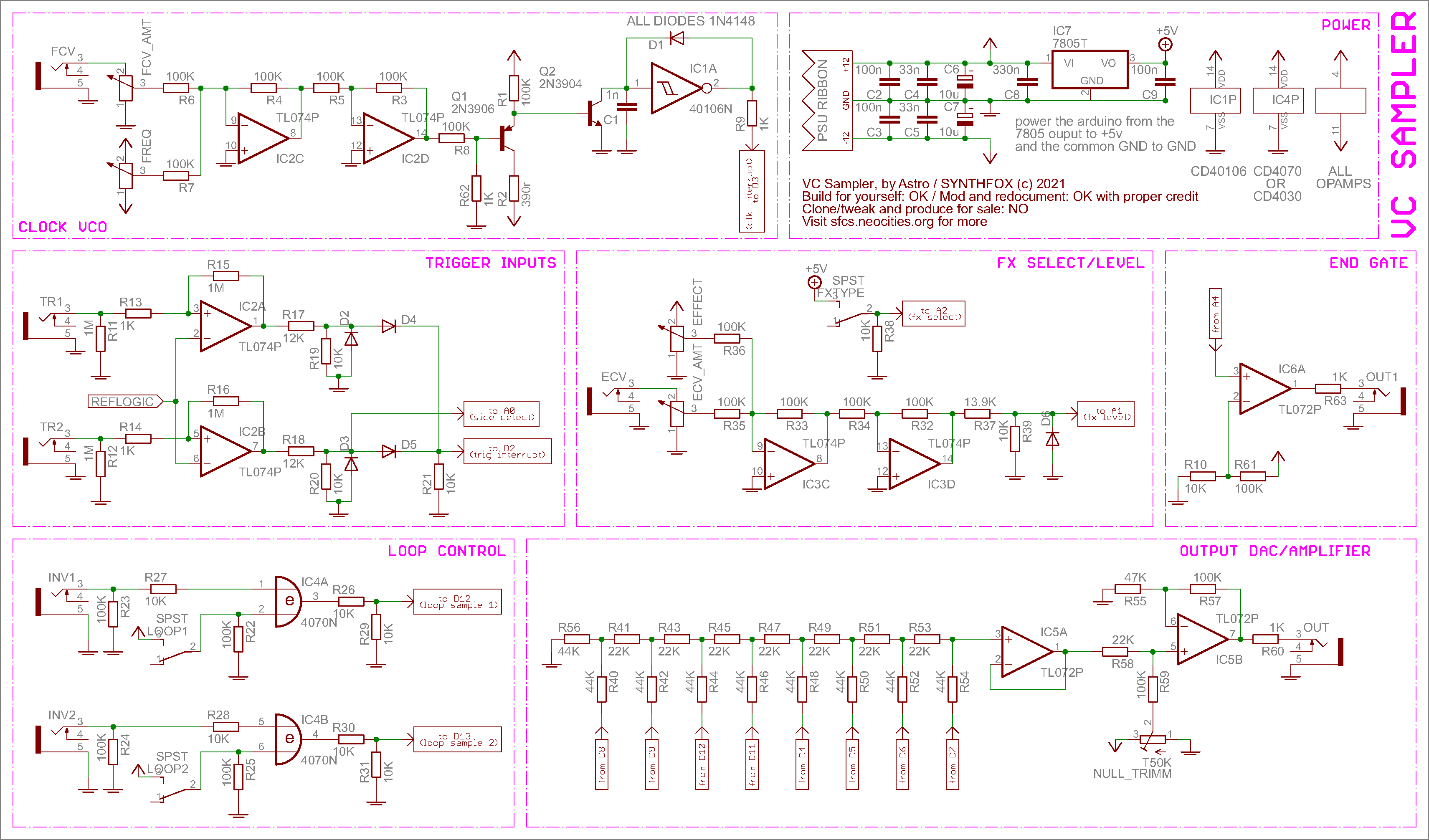
Although not looking like much, this schematic - at least in double - takes up qutie a bunch of space. It's quite complex, but if you have the skill to build this module, you can pretty much tell what's doing what, so i'll just briefly discuss each sub-block. The FROM/TO red rectangles are Arduino Nano pins. The schematic is just for one VC Sampler: my unit is dual.
First, the VCO. It's an analog design, which is basically a ripped-off VCO core from my other module, the Dual 40106 VCO. In fact, the idea to make the sampler dual came from being way too sad using only 1 of the 6 invertors the 40106 provides: now i use two. It's a simple design, and the output of the 40106 provides an extremely narrow pulse. Putting it to the interrupt pin through a voltage divider to drop the huge spike to 5V didn't really work - the pulse was going way below expected, and the uC simply didn't register it. Then i routed it to the pin through a 1K resistor, and so far everything's functioning just fine. (tell me if there's a reason and a better solution)
Under it, there are the trigger inputs. It's just a couple of op-amps as comparators, with just a bit of hysteresis to prevent jittery triggering. Since the Nano has just 2 interrupts, and we're using one to clock it already, i ORed the comparator outputs to the second interrupt that triggers the sample, and put the second sample's gate output to an ordinary pin, with which the controller detects, which sample is played. This means that if both samples are triggered at the same time, the second takes priority. The outputs are put through voltage divider networks this time - it brings them to 0-6V without load, but it goes to about 0-5v when the Nano is connected.
Below it is a loop control circuit - the toggle switches: one for each sample. They are XORed with an external gate ("gate-controlled inversion"). The outputs of the XOR gates go to the Nano pins responsible for loop detection through the same voltage dividers as for the gates.
Up-right of it is the EFX level and selector. The level is your usual dual-inversion mixer mentioned on the Doepfer webpage, but the output is passed through a voltage divider and negative voltage clipper. The 13.9K resistor is obtained by connecting 10K and 3.9K in series, and such a circuit provides the most preciese -12..+12 to 0..+5v conversion out of few parts -you can do it with a trimpot and another op-amp if you want, but do you really want to be that preciese with a crappy 8-bit sampler? The effect select switch is just a switch that connects to 5V in one state and floats in the other. Its middle leg is pulled down with a resistor.
To the left of it is the end gate amplifier - it brings the arduino pin output 0..+ level back to modular -12..+12 hot rectangular signal level.
Finally, below it is the DAC. Mind the pin order!! Any resistors can be used - just make sure they're R and 2R. Using 10K and 22K as R and ~2R will make the DAC sound even WORSE, so better grab a bunch of same resistors and have two of them in series for 2R. The output amplifier supposedly amplifies it to 10vPP, but in my case it turned out to be a bit quieter. The trimmer is to set the null offset for the middle value of the DAC - the sound wave sample oscillates around the value 127, so it's easiest to do on an all-127 sample.
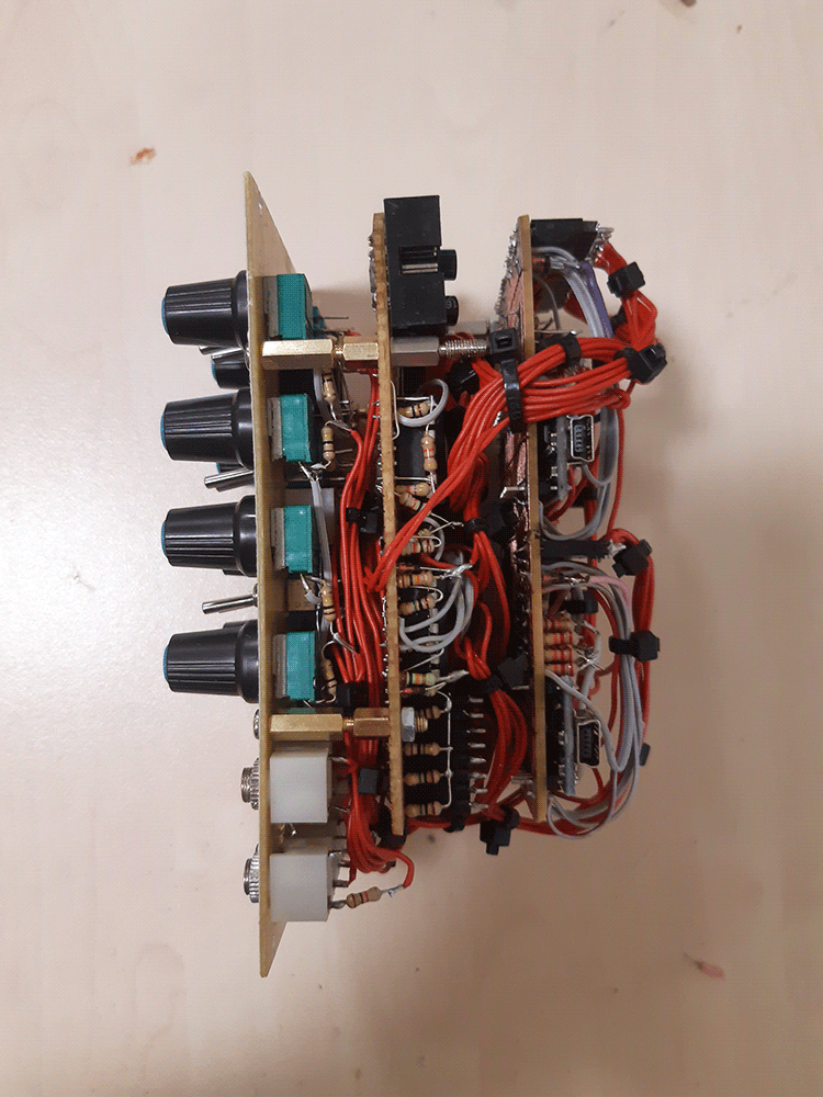
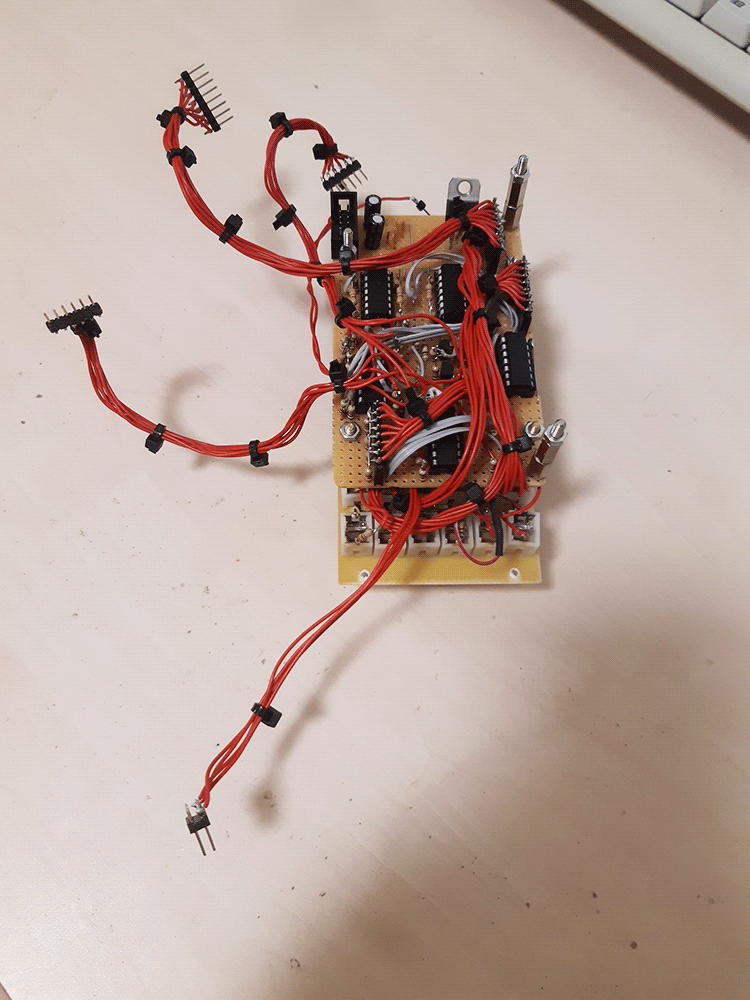
Mind the powering! I used a LM7805 to power both arduinos, and it carries it out easily, but heats up - don't forget to install at least some kind of a heat sink. I did after i took the photos.
All the digital part (code for the arduino and the python console program to convert .wav to a copypaste text that declares array, that you paste to the arduino code) is in the archive that you can download by pressing "download resoruces" below the navbar up there. Also: don't forget to show a bunch of capacitors between +12 and GND, -12 and GND and, ESPECIALLY, +5 and GND. This thing WILL get noisy if you don't.
Media
Just one half, flashed with a bassdrum sample, sequenced with the eight stepper. Sequence affects frequency and effect level.
Cuts of amen break flashed to both sides, one panned to the right, other to the left. Amens are triggered randomly and the pitch is also randomized. I'm playing with loop switches and effects.
A more or less 'full' basic patch with the VC Sampler cycling sinewaves used as a digital complex oscillator. A step sequencer controls the frequencies of the samplers and the timing.
Just a bit more of messing around with one sampler controlling the other's pitch or effect. Amens and sines.
Pictures