About
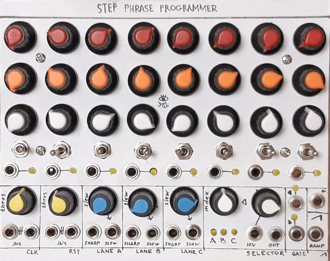
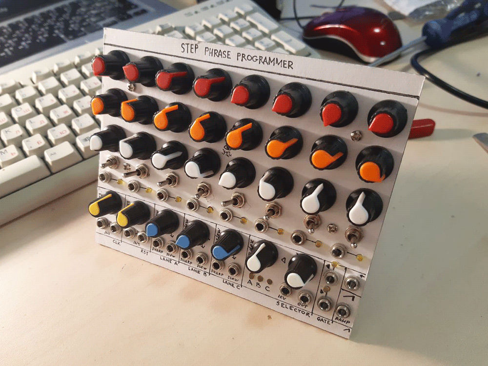
No more! This is it! The buffest, richest, craziest and last rendition of the old good 4017 stepper from my side. One day i just thought - why not to blast all my potentiometers, knobs, faceplate material and willpower on one huge step sequencer? Of course, i have the knowledge and power to make something way, way more sophisticated. But who needs that, when you have THE GODDAMN CD4017, right?! With this, my 'textbook SDIY' gestalt of a step sequencer is now closed for real. This thing has:
- 8 steps (i could make 9 or 10, but who needs that, when you can have the techno stepper?)
- 3 CV lanes with a direct and a slew-limited output, slew rate selectable
- Gate lane with three (right gate on, left gate on, no gate on), output AND-ed with the clock input
- Individual step gate out with an LED
- Clock and reset input, both dual and with a threshold setting, the inputs are ORed before being compared to thres.
- Reset input processed from gate to trigger and doesn't stop the sequence from going after acting
- Another, direct reset input is present: it does, in case someone needed that.
- Ramp output, which goes from low to high voltage gradually along with the steps (handy for VC length and such!)
- VC selector, which selects one of the three CV lanes and passes it to its output
and if this is not enough for a 4017-based step sequencer, i don't know what is. Should i even explain how much fun one can have with this much things around such a simple textbook concept? Hope not! From VC arpeggios, to 24-step sequences, to, well, pretty much all the other craziness that one can squeeze out of this thing. Only thing i have to mention is - this build WAS a pain in the ass, took me a long time and a lot of parts, so if you're not a moderately skilled SDIYer, better make a simpler, classic 4017 CV sequencer first: there's a whole ton of way simpler designs out there in the internets.
UPD 13 March 2021: a mistake in the schematic was pointed out by Subjectivize - i left the gate output LEDs not marked on the schematic. Fixed, thank you!
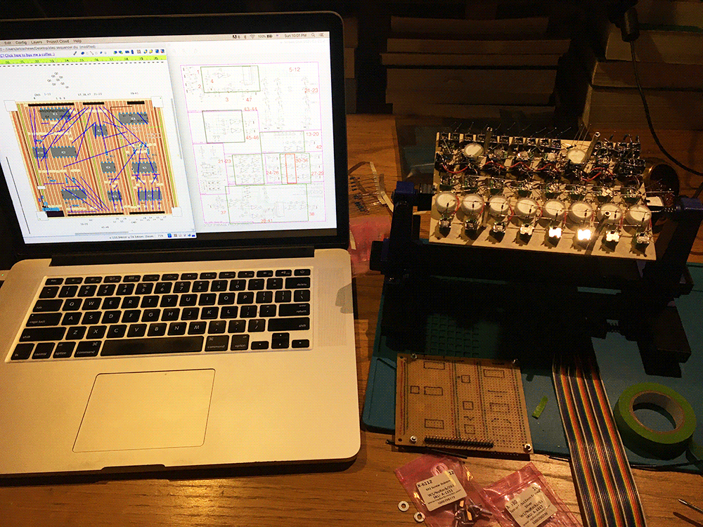
Schematic
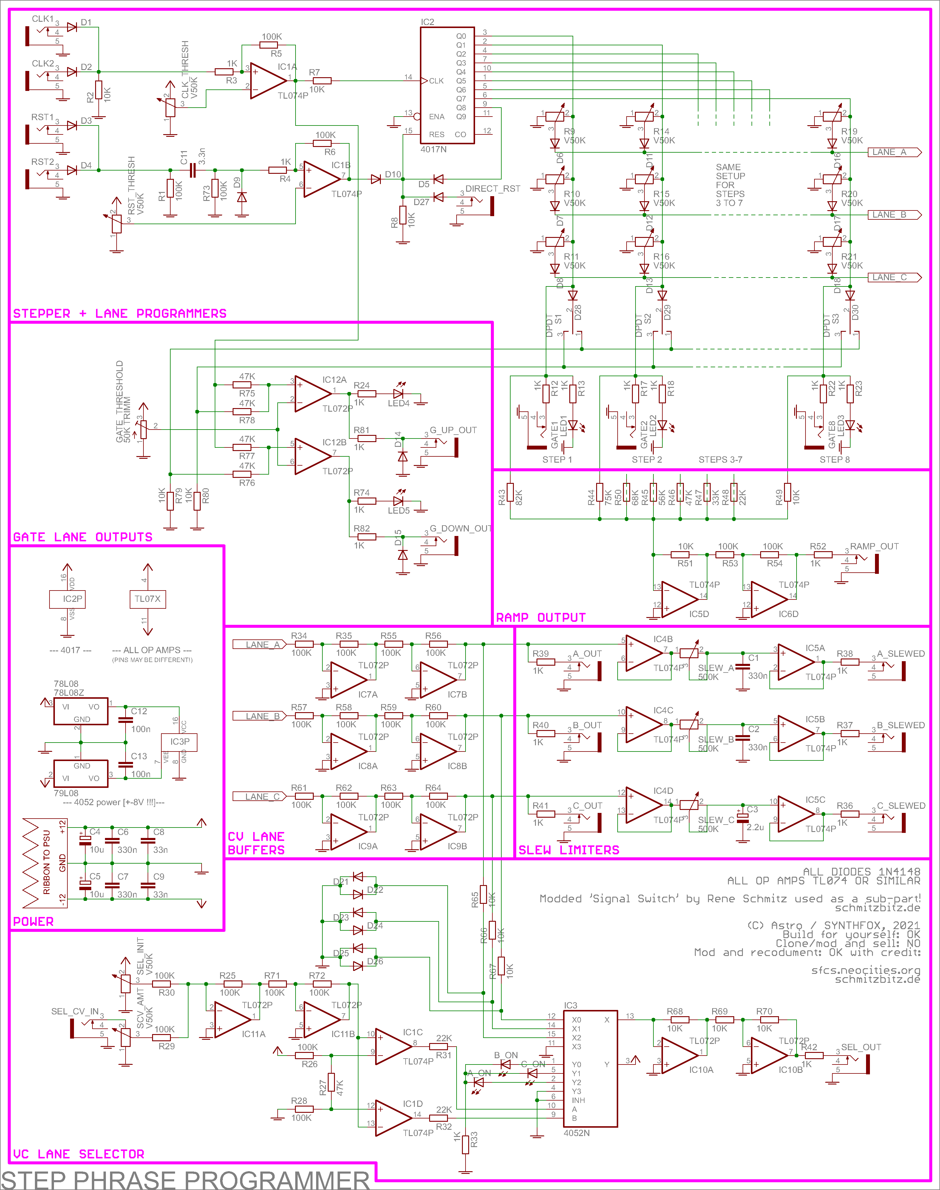
I divided the schematic into parts with the pink lines, and each part has a name in the bottom left corner. To easier explain what's going on, i'll go over each of the blocks.
First up is the stepper and lane programmer block. IC1 is a dual op amp (can be part of a quad op-amp, like in my case - doesn't matter!) and it processes clock and reset input. Clock is just being compared to clock threshold value and passed on to the 4017 CLK input pin, and reset is being converted to trigger with an op amp first - note the whole setup around C11. It's then diode-ORed with output 8 (9th step) of the 4017 to limit the maximum sequence length to 8, and with a direct reset input - it's designed to be used with 4017's own gate outputs and is vastly untested with stuff like sound etc, to it has the literal single purpose - be a faster reset input to hard-set the sequence length. Then we have the classic 4017 CV sequencer setup: output pin to potentiometer right leg, ground to left leg, and wiper leg diode-ORed (to prevent crossfeed) with all other potentiometers for other channels. The output from the diodes is the basic CV line output. There's three CV lanes like that. Below are the gate lane and the individual step gate outputs with LED indicators: mind the diodes before the switches for the gate lane to prevent crossfeed.
To the left of this block is the gate lane outputs - also a simple op-amp based construction. It's a snazzy little trick i did to avoid using the 4081 AND gate and BJT transistor logic. The gate lane outputs are passively summed up with the clock signal comparator's output, which means that the sum will have three states: 0 (clock fell and gate is off), about 6V (clock rised, but gate is off, OR gate is on, but clock is down) and about 12V (clock is up and gate is on). The trimm potentiometer out there is to set the point between the about 6v and about 12v state to use as a threshold for the comparators. This way, the outputs of the op amps only turn high if the clock is high and the gate is set. This means that if we set, say, all gates to the right, we won't get one continuous high signal, but instead a copy of the clock signal (as the module sees it post-comparator). This is important for drum sequencing, cause otherwise it'd be impossible to program two consecutive drum hits: they'd merge into one.
The ramp output block to the right of the gate output block is a very simple part - it just puts gates from 4017 through different resistors with the values selected such that it creates an uprising staircase voltage at the output as the sequence progresses - from step 1 (lowest) to step 8 (highest). It's very handy to use it with an external comparator module to, say, program voltage-controllable events based on the sequence step, or do stuff like voltage controlled pattern length. Mind the dual inverting op amp! It has to have virtual ground at the junction of all the resistors (r43-r50), otherwise step crossfeed will happen and the thing will go nuts.
Below is the CV Lane buffers, which are just two unity gain inverting amplifiers per lane - this is because otherwise the VC selector part won't work properly, + drawing CV directly from the post-pot diode OR junction would be unstable, as it'd drop differently depending on the load.
To the right are the slew limiters - one per channel: a classic slew limiter/lag processor op-amp based little circuit you can find in the first results of the image search. Nothing too special about it, but it adds a whole bunch of possibilities and new sequences! The best cap value is 330n, but i did one 100n (for antialiasing if i use it as a wavetable subdivider), one 330n (normal) and one 2.2u polar cap (slow ambient with one step per minute sequences). So, it's a matter of taste!
Now for the part that takes up the least space on the faceplate, but is actually the toughest to comprehend: the voltage controllable lane selector at the very bottom of the schematic sheet. It's based on CD4052, a 4 to 1 multiplexor/demultiplexor. One of the four in(out)s is routed to the common out(in), depending on the logic values at inputs A and B (possible combinations are 00, 01, 10, 11). I exploited this chip's binary control to actually select between one of the three lanes with voltage control: its select (A, B) inputs are driven by a pair of comparators. The comparators process a sum of CV and initial 'index' setting: the output of the op amp comparator on the top goes high when the sum is above about 7.1V, and of the one on the bottom goes high when the cv+index voltage sum is below about 4.8V. This way, sweeping the index from 0 to 12 would generate first 01, then 00, then 10 at the AB inputs of the 4052, thus routing inputs 2, 0 and 1 (in this order) to the common outputs. One in/out group is used to drive indicator LEDs, the other is used to route the CV lanes post-buffer. The switch circuit (the whole diode clipper and 'no voltage' trick) is courtesy of René Schmitz, a person you've surely seen schems of if you've stuck around SDIY for a while. Big up for René and his creativity! The module i adopted the design from is called 'Signal Switch', check it out on his page. I made little changes to it, but overall the fact that the switch works so perfectly is all thanks to mr. Schmitz.
Pay attention to how the CD4052 multiplexor IC has to be powered from +-8v! It can be easily done with 78L08/79L08. Powering it from +-12v will fry it.
And that pretty much sums it up. Now, is THIS enough heckery for a 4017-based stepper? I sure hope so. Good luck and have fun!
Media
Demo of the selector thing - note how the melody shifts between three 6-step patterns. That's because 7th step gate is fed back to reset in, and the selector is controlled by an LFO.
Using a comparator from Arithmetics to compare the ramp output and a precisely shifted and offset LFO, so the step the comparator fires at bounces from 2 to 9/none (full length).
It's possible to get 16-step sequences by running the 1st gate output to a binary divider, and using the /2 division as a control input to the selector. Here's a little acid sequence of 16 steps long. I'm using the subharmonic generator as a divider, so i end up kicking in slower subdivisions and getting even 32-step long patterns with one repetition of 8 steps.
I put the Doepfer A-118 random output to the clock input. Now the threshold setting determines the rate of random clocking of the sequencer! I also put all the gate lane to the right to use it to trigger a decay envelope every time the clock fires.
A little demo of controlling all parameters Meng Qi's Karp with my sequencer unit.
A full patch demo, sequenced almost entirely by this sequencer.
Pictures

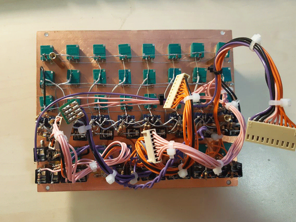
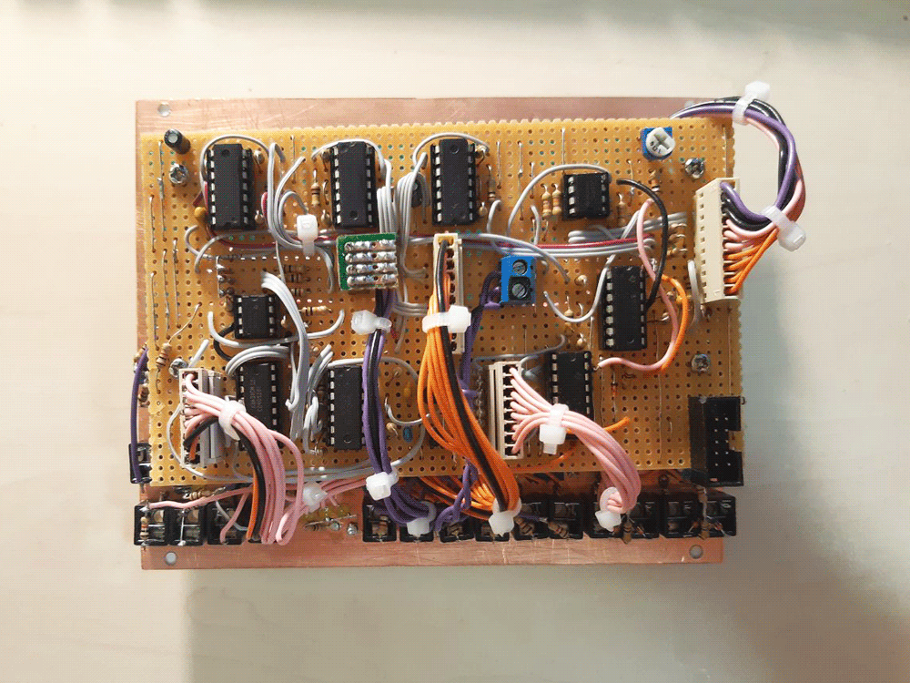
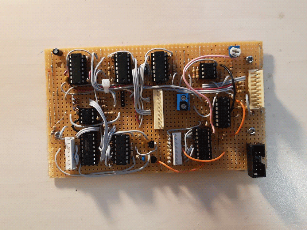
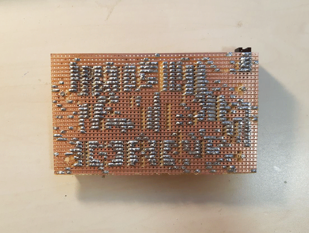
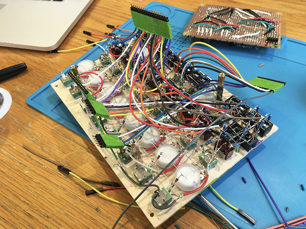
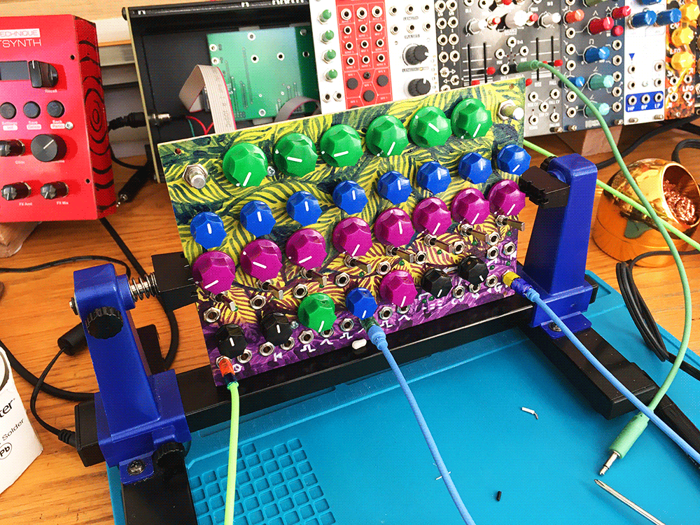
subjectivizeit's build