About
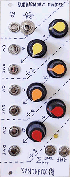
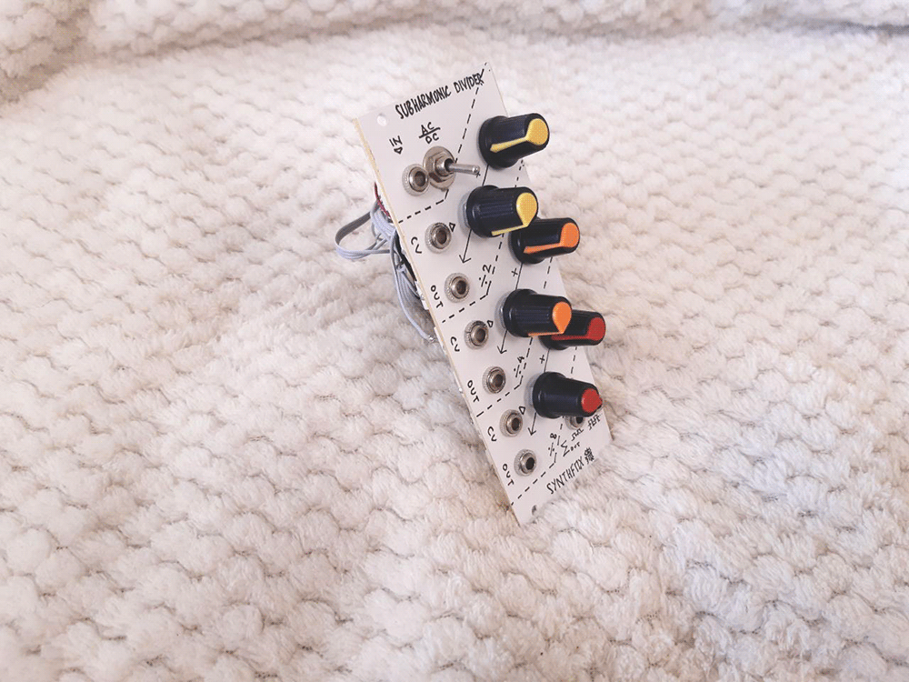
Subharmonic Divider is a sound processor which tries to generate suboctaves from a given sound. With pure wave like a sinewave - folded or not, or a sawtooth, it will do its job perfectly and generate three subharmonic squarewaves: at -12 semitones (2 times lower frequency), at -24st (/4), and at -36st (/8). Each subharmonic is then passed through a special VCA circuit which gives control over the subharmonic's volume with an initial volume knob, and also can be modulated with external control voltage. All three VCAs have separate outputs, as well as a summed-up output at the bottom of the module. The input has a toggle switch that changes between AC (best for sonic range signals: detects frequency by zero-crossings and the input is AC coupled), or DC (best for clocks/LFOs, detects freuqency by about 1/11 of positive supply, DC coupled input). The output comes in two flavours: DC sum out (just the sum of the VCA'd subharmonics) and AC sum out - that is the DC out, which is passed through a slight antialiasing lowpass filter and a decoupling capacitor. This way, by having the ability to process and output DC coupled signals, the module can also become a clock divider, or a sequencer. It also gives very interesting results with FM tones, guitar chords and different flavors of noise.
Schematic
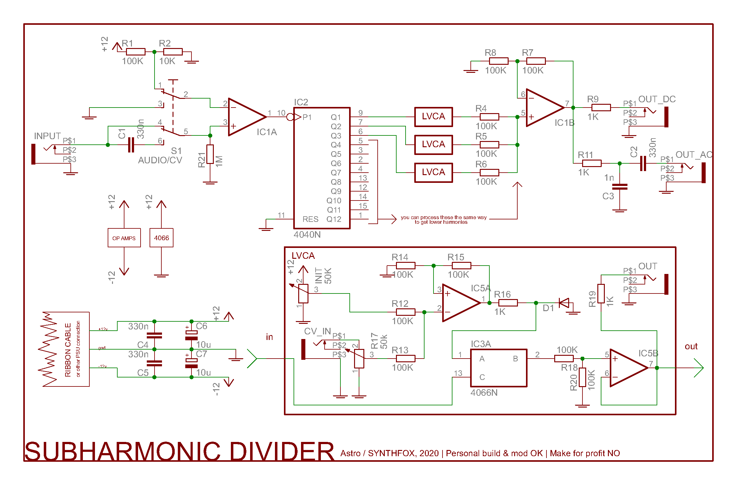
This thing's design is pretty straightforward. First, the signal is compared by IC1A - almost any op-amp, i used TL072 - to either 0 (in case we AC couple it) or about 1/11(VCC) (if we keep DC coupling). Then it is passed to a CD4040 ripplie binary counter, which effectively spews 12 subdivisions of the pulsewave that the comparator gives out, each one 2 times lower than the previous one. Any of these subdivision outputs can be passed through a circuit that i call "Logic VCA", or "LVCA", and summed up around IC1B, the other half of the dual op-amp. The output of the op-amp is then available directly through a 1K output resistance, and through an antialiasing lowpass and AC decoupling capacitor - DC and AC outputs, respectively. So far it's nothing harder than just taking a bunch of signals and mixing them! The only tricky part is the LVCA guts.
Amplitude modulation of a squarewave could be done with a CD4066 bilaterial switch used in a non-conventional way. We usually think of logic-controlled analog switches as something that passes or blocks the signal depending on the logic state of the controlling terminal. One could think, that to make it a VCA, we should somehow convert the binary control into analog control. With this IC it is, of course, impossible to do so - you need a proper VCA to control an amplitude of any sound in general with an external voltage. But for squarewaves, we can use the 4066 the other way around for amplitude modulation: now the controlling terminal is the input for our squarewave, and the input of the switch is the CV in! Simply, by opening and closing this switch with a squarewave (or pulsewave) signal, we are outputting whatever is on the switch's input, or silence, one then the other, at a frequency that is the same as the frequency of our squarewave. This way, we get the same squarewave at the output, but its amplitude is defined by the voltage at the input of the switch!
Because of the 4066's nature, we should buffer the input and the output of a switch with op-amps. The input is from an op-amp summing the initial amplitude control and the external CV for amplitude put through an attenuator. The output gets halved in amplitude with a voltage divider to give headroom to other subharmonics in the mix, and is buffered by another op-amp. An individual output jack is connected to it through 1K output impedance, and all the outputs of the LVCAs make up sum outputs.
There are two drawbacks of such LVCA circuit: one is that it will be bleeding a little bit. A very neglectable little bit. It is fixable by adding a trimming potentiometer into the sum of initial and CV and adjusting it until the bleeding is gone with the initial fully CCW and nothing at CV in. The other drawback is that it has a little thump when the CV drops below zero. Again, the combination of initial offset and attenuation of the CV can help to get it to positive half only, but there's this issue and so far i had no luck in fixing it. Using different diodes for D1 gave different results, the best ones so far were the classic 1N4148, and the shottky diode BAT-48.
I only put the upper 3 divisions of the 4040 binary divider through such LVCAs, so i can have up to 3 suboctaves. You can do all 12, if you want, so that you can even derive clock signals from audio VCO frequencies, or use it as a crazy sequencer of a sort. It's all up to you! Also, note that there's no sum out LED indicator on the shcematic but i have one on the module. That's because it works strangely and i decided to omit it. If you want to add one - be sure to drive it with a transistor at least, or use a spare op amp for that, if you happen to have it on the board.
P.S. i thought of the LVCA concept about 3 years back, and searched up if it was a thing already. Some person on either electro-music of muff wiggler had the same conept in mind, and had a post where they said it's working. I can't find the topic, but if not you, i probably wouldn't dare to try implementing it that easily! Thank you! If someone recalls the topic or the person - contact me for crediting.
Media
Korg MS-20 Mini output fed through its own amp section and put into the subharmonics divider. The sum output of the divider and the ms-20's phones out are mixed down for the final sound. First few seconds is the original korg tone, later on i'm playing some notes and twiddling some knobs. Note how interesting is the suboctaver's responce to higher VCF resonance values!
A little self-playing patch showing off the capabilities of voltage control over octave loudness: 3 sawtooth-ish LFOs are tapping the suboctaves' volumes, and some other internal stuff intermodulates the LFOs and makes a VCO that the harmonic divider is processing jump between the two notes.
Syncing the module to the same trigger that fires a silly sawtooth and vcf voice, and using the DC sum out as a sort of a sequencer!
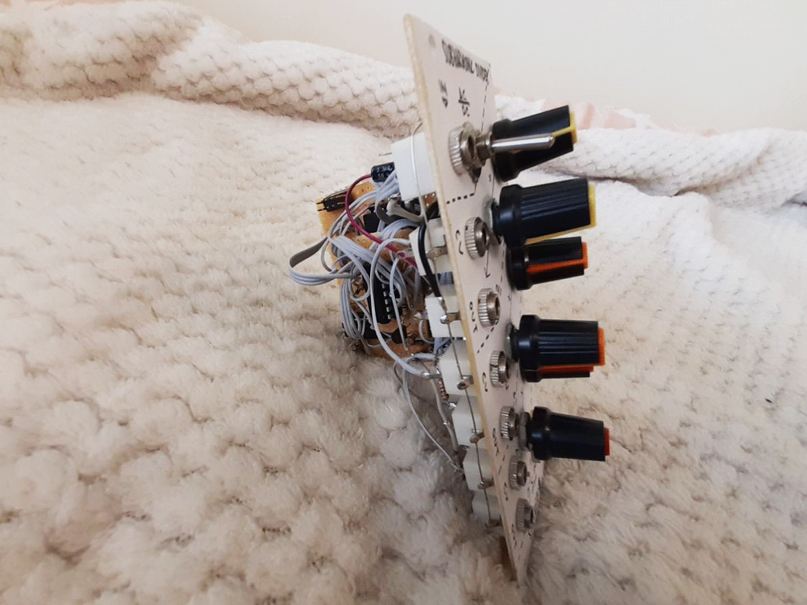
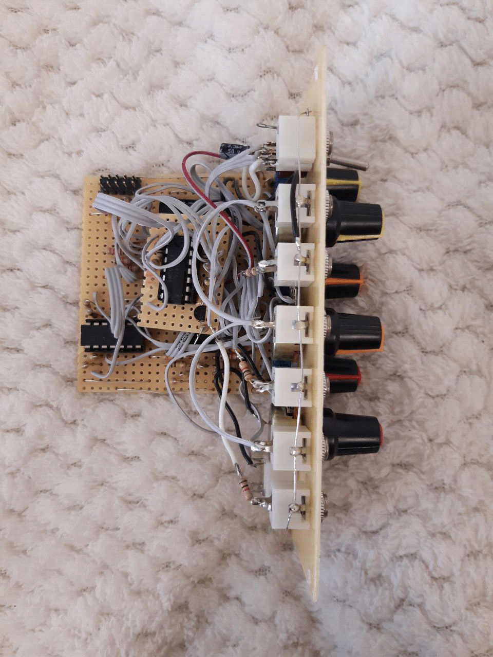
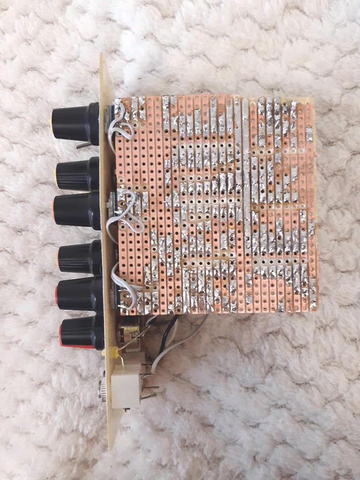
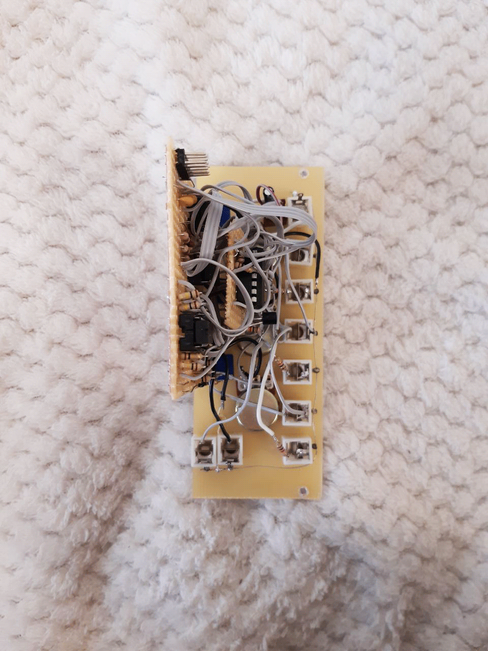
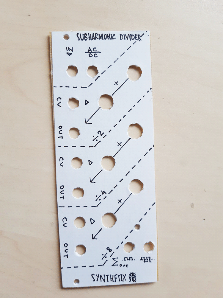
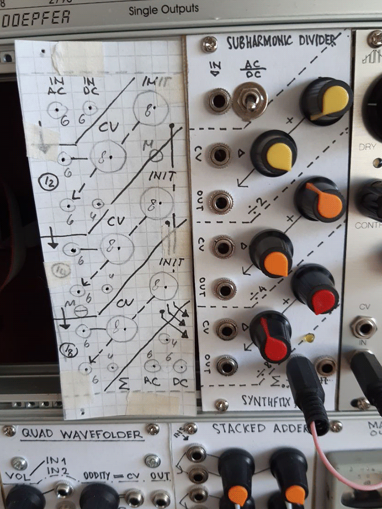
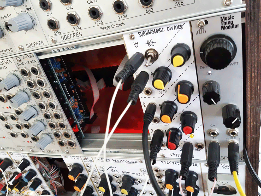
Pictures