About
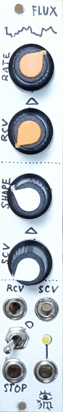
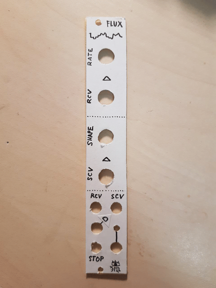
This weird entity captured behind a rack panel has just one output - the one, at which it outputs a pseudorandom fluctuating voltage. The kind of voltage that is generated is controlled by two CVable parameters: rate and shape. Rate controls how fast the flux will change, and shape sets the smoothness of the resulting wave - from a barely existing smooth wobble to a sharp staircase. There's also a direction switch that allows to ignore the shape setting and let the voltage jump really quickly in one direction or another, making sawtooth-like and reverse-sawtooth-like voltage blops at the output as well.
Because the semirandom flux generator isn't based on any true random source, like white noise, but instead uses four VCOs as its generating core, it's formally possible to predict all its future states for an infinite amount of time. Yet, the voltage fluctuations can be rather unpredictable, or - in countrary - start to pattern up and form weird ornaments. If you turn the speed knob up and back down to the same position, you never will get the same kind of "patternoid" to happen. So, even though it's not any sort of true random, it's very interesting in its semi-patterning behaviour!
The stop input was meant to pause the generators on a gate, but didn't work well at all, so i omitted it on the schematic.
Schematic
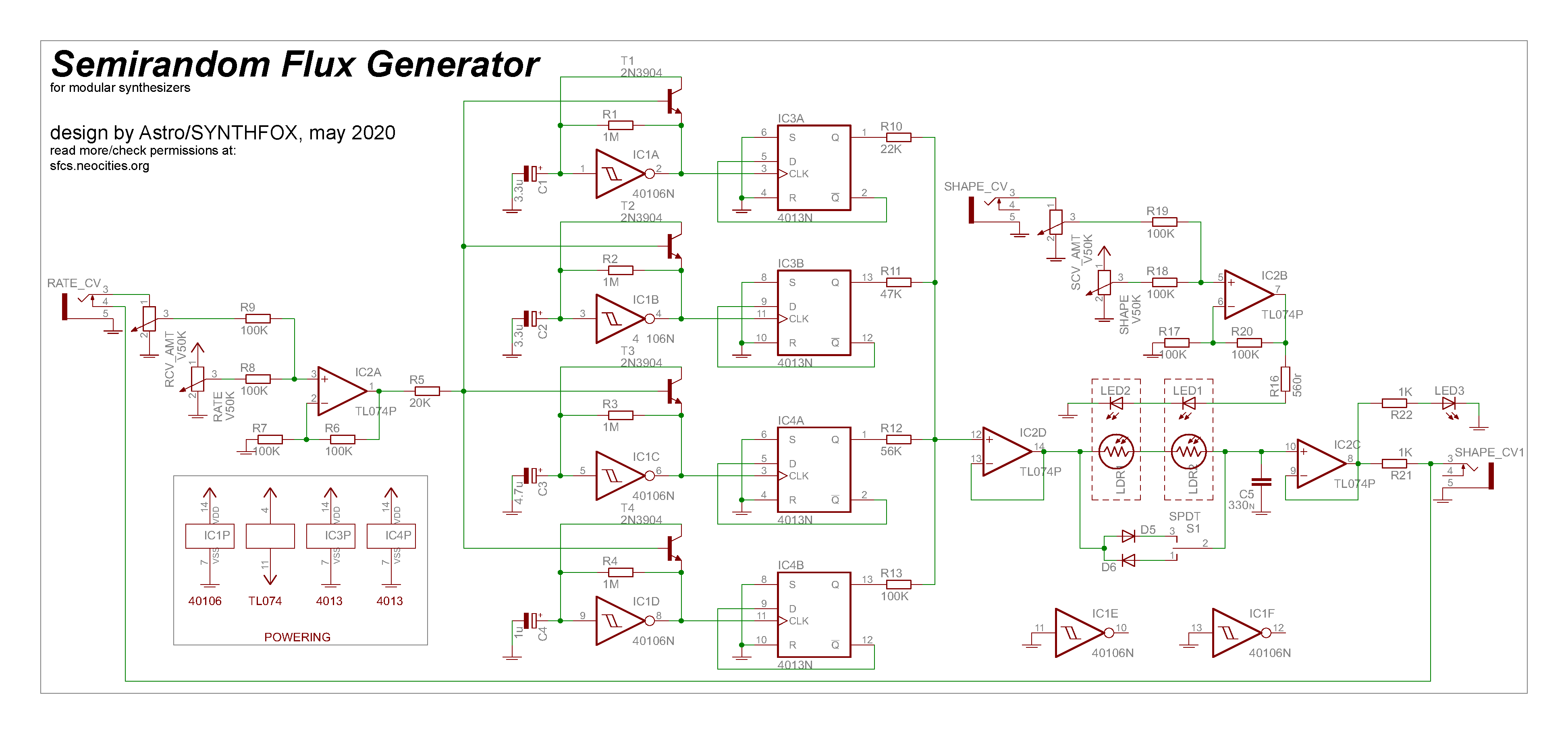
This isn't an exquisite cirtuit - it's actually quite hefty for such a simplistic thing. The circuit consists of three main stages: VCOs, summator, and slew limiter.
Four simple pulsewave VCOs are made on just one CD40106, and then each output is divided and symmetrized into a neat squarewave by a half of the CD4013 set up as a /2 frequency divider. All VCOs are controlled by one voltage, which is the output voltage of the non-inverting summing amplifier (IC2A). It's possible to break out every single VCO control the same way, but R5 for every summator has to be raised to about 100K. It's also possible to play around with R5's value in the by-schematic build: decreasing it to 10K led to the unit being able to reach audable mids, but also seemed to have decreased VCOs' stability.
The summator is just a voltage follower after a sum-up of divided VCO outputs through different value resistors. Keep in mind, that if you use same resistors, you will get fewer pseudorandomized steps, which is not good. Playing around with these resistors' values (R10-R13) is also up to the builder's taste.
Finally, the mix is smoothed out by a vactrol-controlled slew limiter. It's a very simple textbook slew limiter, or lag processor, except the potentiometer is replaced by two LDRs in series - each in a lightproof heatshrink casing with the corresponding LED, forming a vactrol. This is also where the direction mode switch is - it's allowing the signal to "jump over" the LDRs in one direction or another, or not pass it at all. Be sure to use a dual-throw switch here, otherwise you'll never get the smooth trianglish fluctuations.
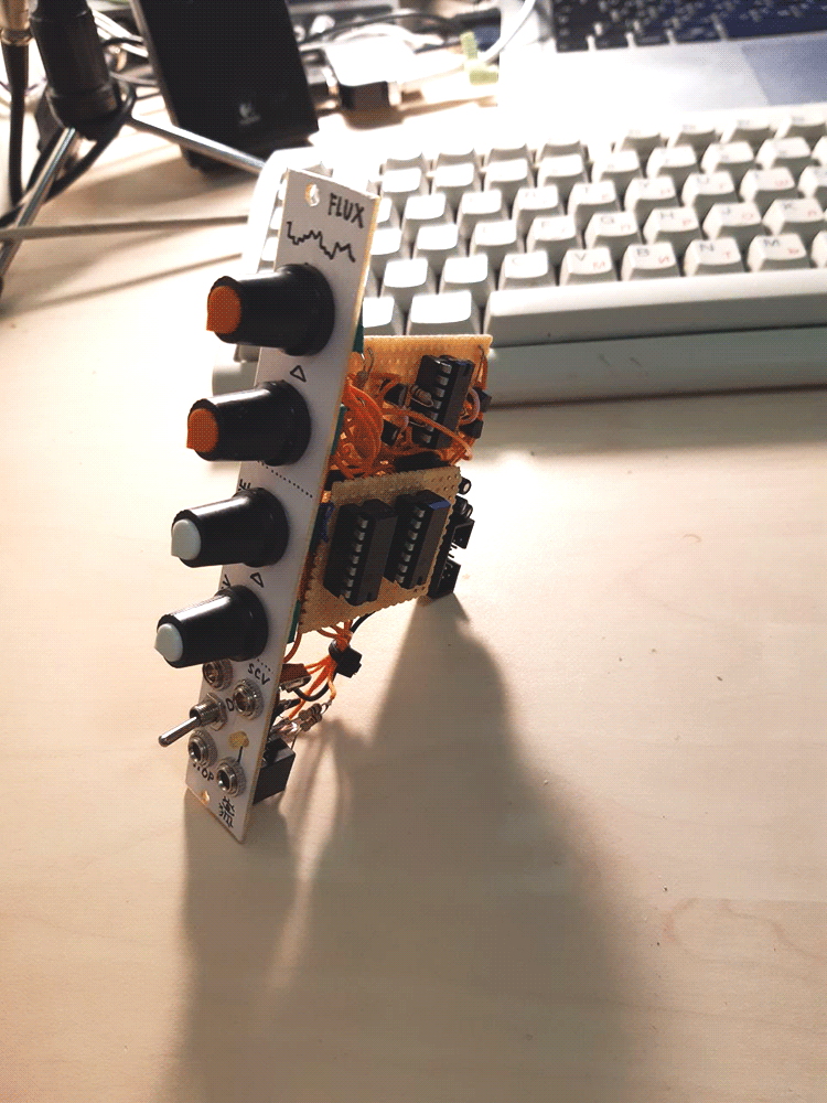
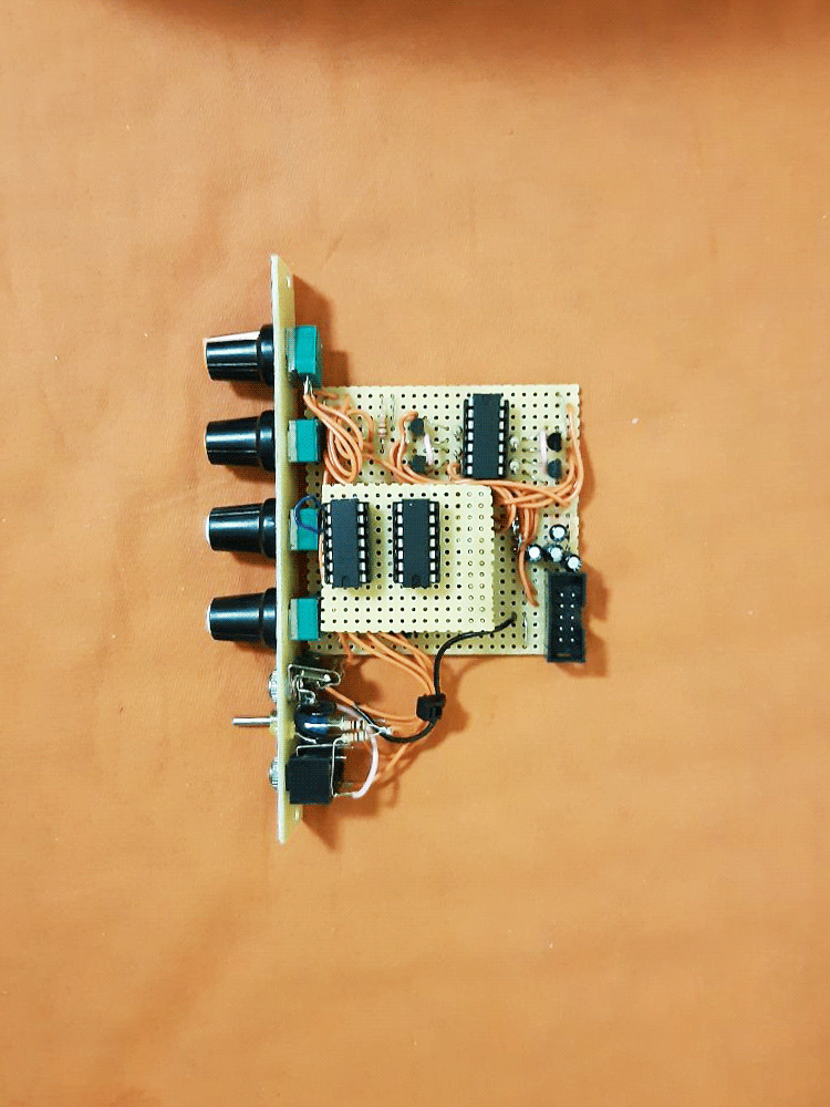
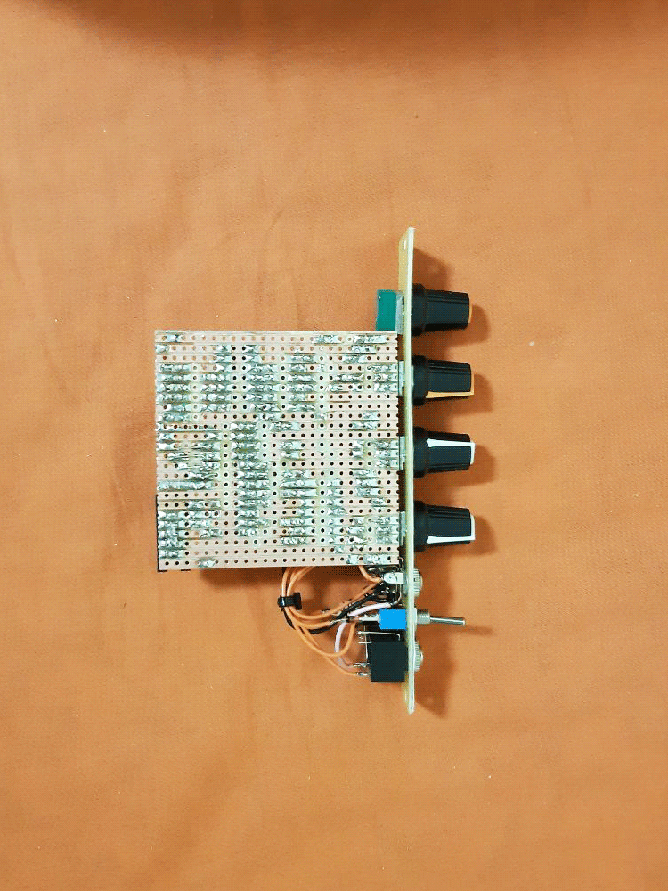
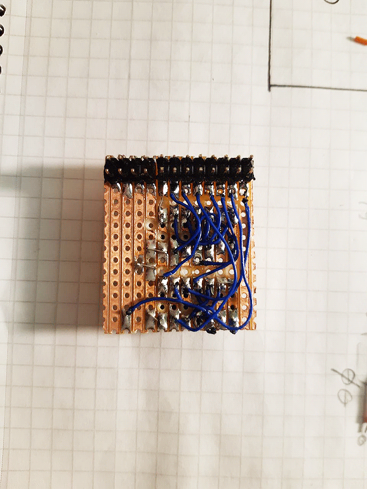
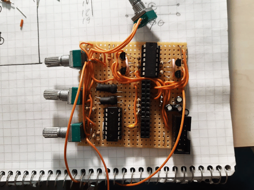
Because the module has so few controls, i decided to build it in a very narrow rack panel. As a result, i had to make an insanely small frequency dividers daughterboard to fit it in, and this definitely impacted my brain's well-being for a while. If you are actually going to make it - make it BIGGER, or be ready to scream (refer to the pictures below). Also i wouldn't recommend this project for a beginner SDIYer. Maybe try the very cool Directional VC Slew Limiter first - it can be an interesting LFO, a filter, and whatnot else, but won't burn your nerves!~
Media
Playing around with the knobs, the output controlling an FM pair.
Same as above, but the direction mode switch is in effect, and only one sinewave VCO is left to listen to.
Pictures