The same question has been asked countless times at the SDIY corners of the internet: "how do you people make faceplates?"
This article explains my method of making eurorack paperface panels. It's a very budget-friendly, non-demanding method that is possible to do even in the most limited of accomodations. It requires a limited set of tools, most of which most people already have. It's a fun method, and the results look pretty exciting, too! In this guide, all steps of the making of a panel for my Jelly VCF is shown as an example.
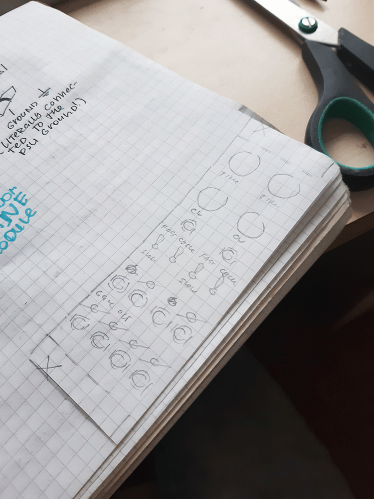 |
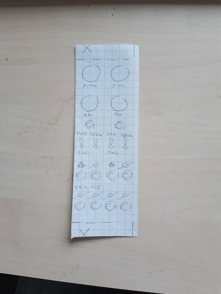
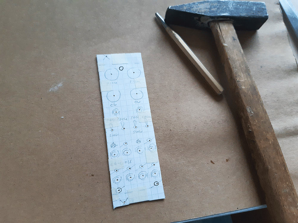
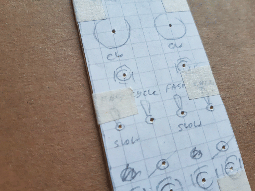
Start off by designing the panel layout on a sheet of paper. Using a 5mm grid paper is easy, since the height of a eurorack module (128.5mm) can be rounded up to 130mm with 10mm rail padding on top and bottom. Info on hole placement can be found on Doepfer's construction details page, but basically it's 7.5mm from the left and 2.5mm from the top/bottom - about 3mm if we approximate the height as 130mm. I suggest doing a bunch of drafts before coming up with the final solution. 10mm horizontal and 15mm vertical distance between jacks/switches and 20mm between pots, as well as placing future drill locations on the 5mm grid is advised. Once done, cut out your layout and set it aside. |
 |
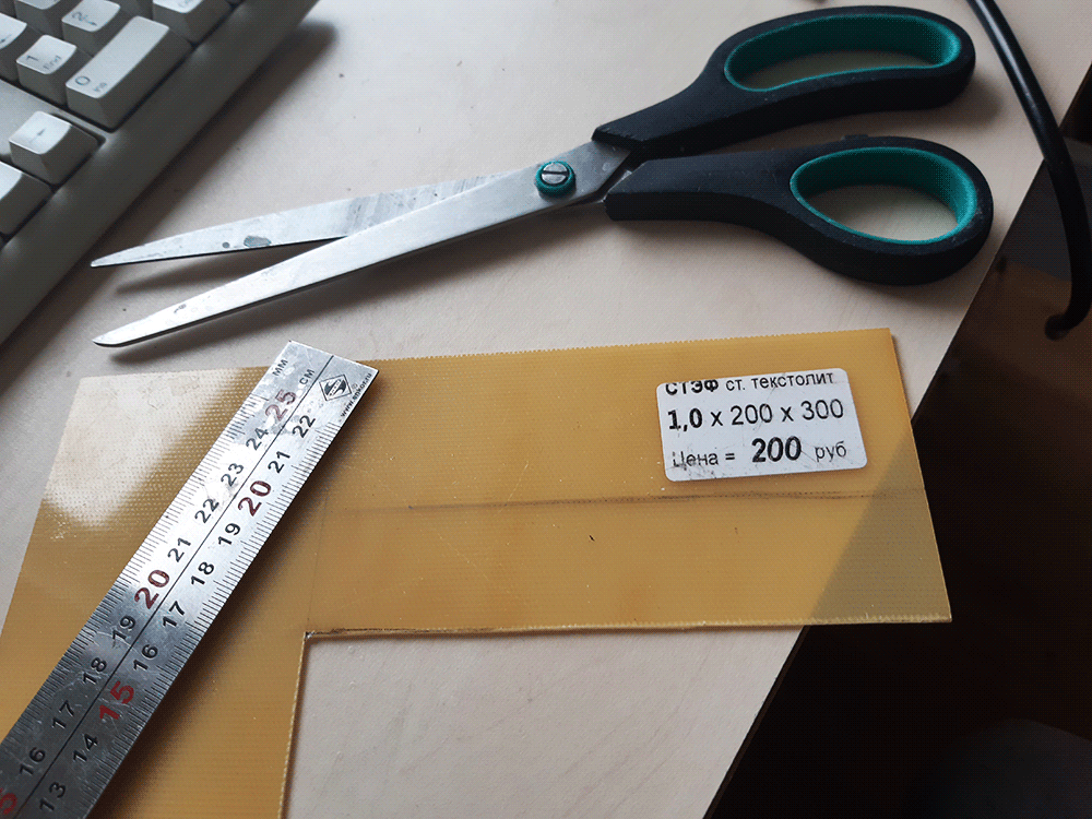
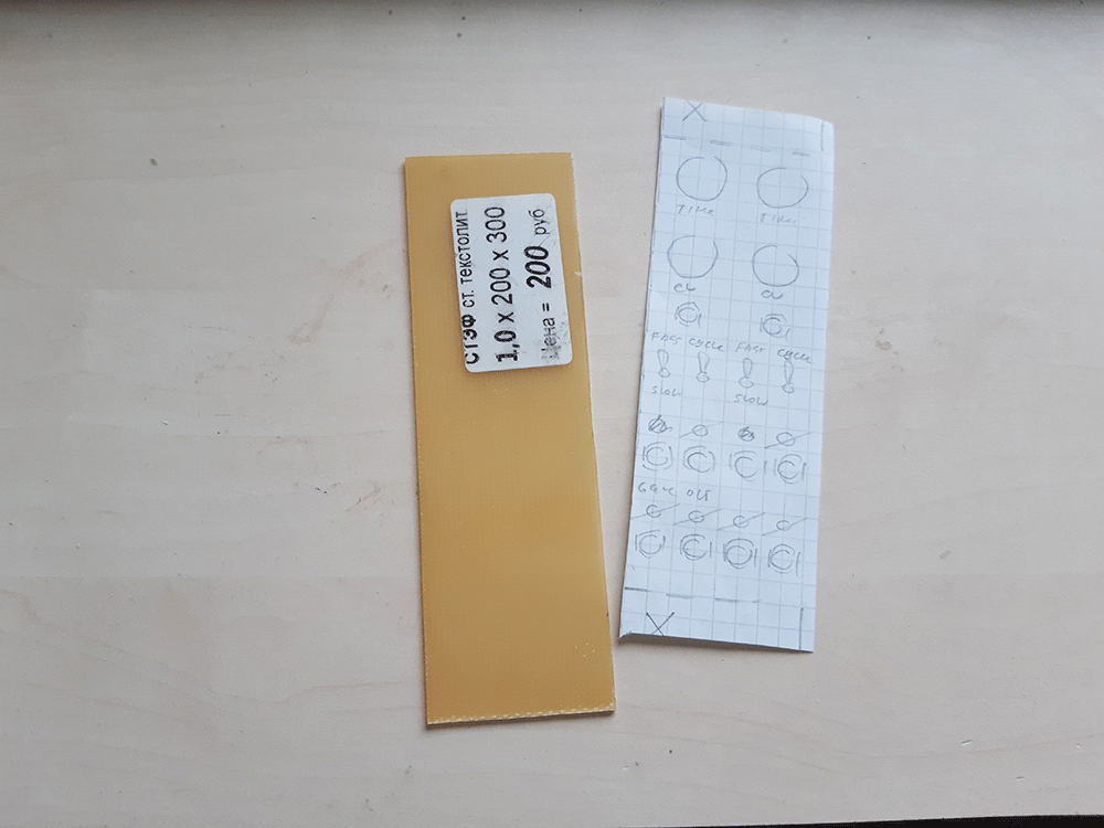
Take a sheet of single-sided 1mm thick FR4 textolyte, draw out a 129x(N*5)mm rectangle. Technically, one eurorack hp is 5.08mm, but i ditch that for easier build process and don't care - and neither should you, as long as you use sliding nuts for your case. The textolyte's copper side goes inwardsd, towards the PCB. It's very handy because once you mount the 3.5mm jacks, their ground legs can be simply pushed towards the panel and soldered onto it, further solidifying them in place and removing the need for a hefty long bare groundwire. |
 |
Cut the rectangle out with some heavy-duty scissors. A long and mid-grain file can help straighten the wonkiness of the hand-cutting. I also like to prepare the surface for further jack ground leg soldering by mildly roughing it up with some fine-ish sandpaper. |
 |
The height of the rectangle i draw out is 129mm, both to use the actual measures printed on the ruler and to have some headroom in case my hand slips and i cut a bit too inwards. Fitting the panel to the rack will reveal if it's too tall. Usually it is, but also the top/bottom cuts end up not perfectly parallel or wonky, so filing that down with a file to a nice 128.5mm is better than trying to cut out 128.5mm sharp from the first go. The panel should fit without force and have a tiny bit of wiggle room vertically. |
 |
Now flip over the panel to the side without copper and stick the layout drawing on top of it. There is likely some vertical overshoot on the paper, since it is 130mm and the panel is 128.5; you can cut it off, or simply ignore it and do your best to center the paper. I usually fix it using some tape on the sides. The paper should not be bulging or creasing, and lay firm and flat against the panel's surface. This and the few following steps are crucial to the outcome; take your time, do not rush, align everything well and be as precise as you can. |
 |
|
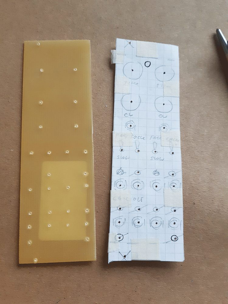 |
Now take a hole punch, a hammer, and hit the panel where the holes go. Use the legend drawn on the paper to place your hits - sticking to the paper grid pays off in this step, since the guide ends up very precise. Having enough lighting at the working zone helps makes precise punching easier. If no dedicated punch is available, an old drill bit no longer used for drilling is an alright alternative. Make sure to not miss a single drill point - it will be hell reapplying the paper "as it was" later if you do! |
 |
Peel off the paper and set it aside. You should now have a bunch of nice marks for drilling on the panel. |
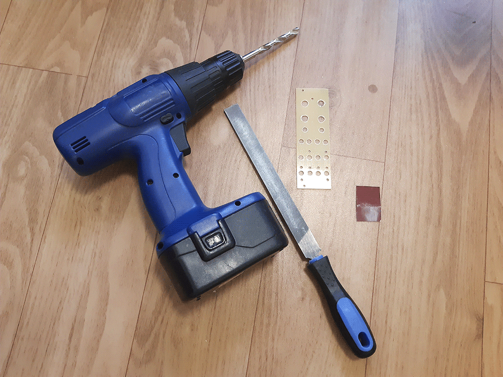 |
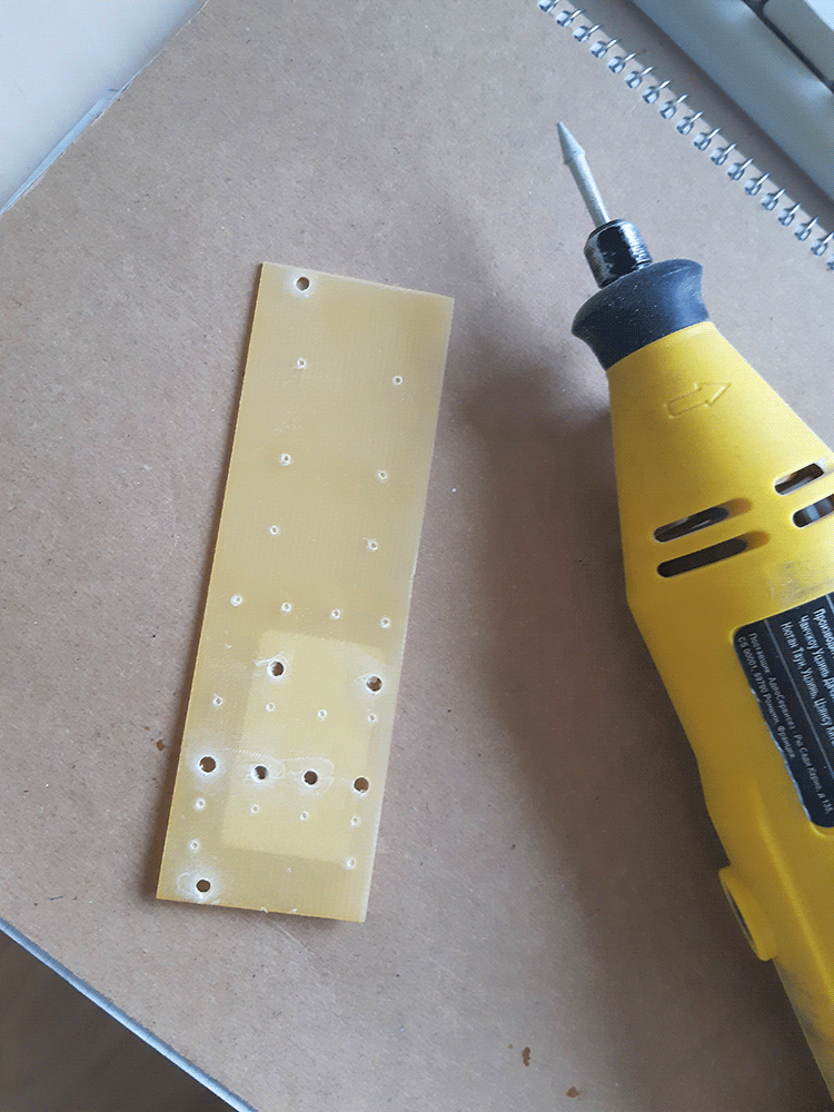
Prepare an electric screwdriver (no need for a power drill) and the drill bits you need. 3.2mm for mounting holes and 3mm LEDs, 6mm for jacks and switches and 8mm for potentiometers is usually enough for me. Universal or metal drills are OK; wood or concrete ones not so much. I do the drilling on top of an old wood plank that i happen to have in order to not drill into my flooring. |
 |
The 3.2mm drill bit goes first. Wherever a 3.2mm hole is needed, drill through. But on all other marks, do a little pilot drill-in without going all the way through. This further reduces the wobble the bigger bits experience. |
 |
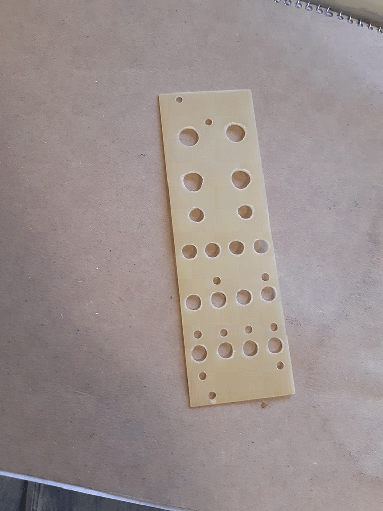
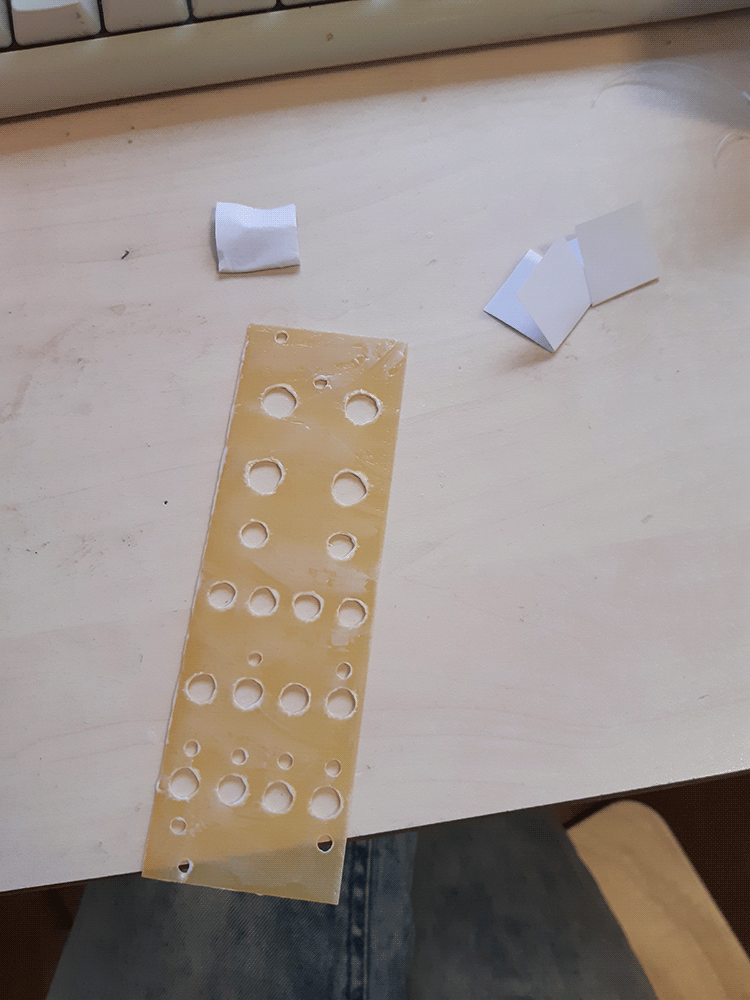
Drill the bigger holes. You will end up with a lot of burrs and debris stuck to the hole sides. The first wave of help is to scrub the panel with the file's flat side, removing the bigger bits. The file's corner can then be inserted into each hole and twisted back and forth, removing smaller burrs. After that is done, sandpapering both sides of the panel makes it look and feel nice and smooth. |
 |
|
 |
|
 |
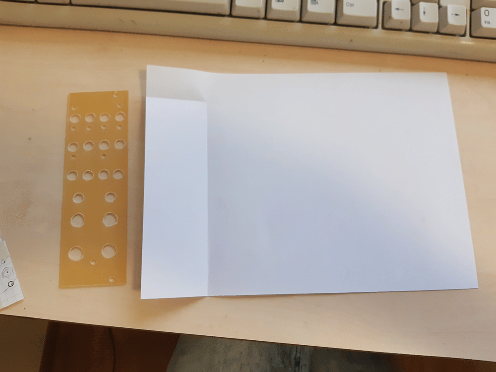
Take some usual office paper, cut out a piece that's the size of the panel padded by about 4cm on all sides, and some assorted small pieces. |
 |
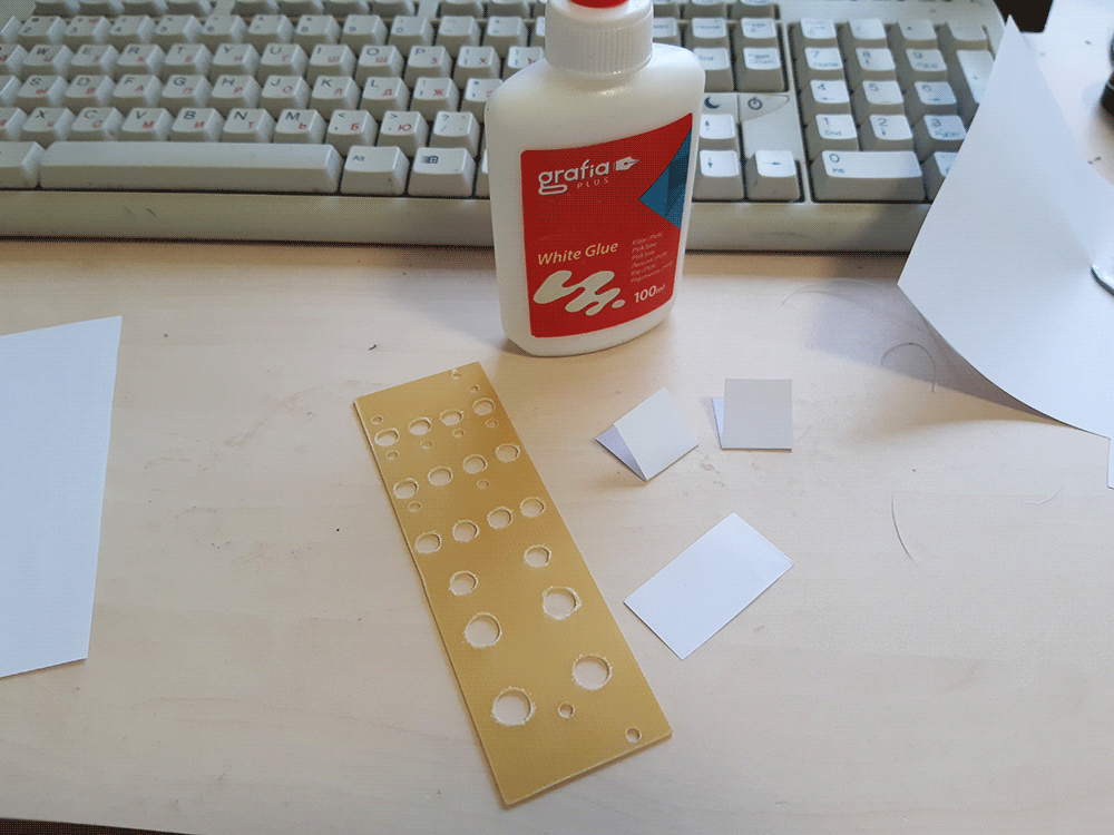
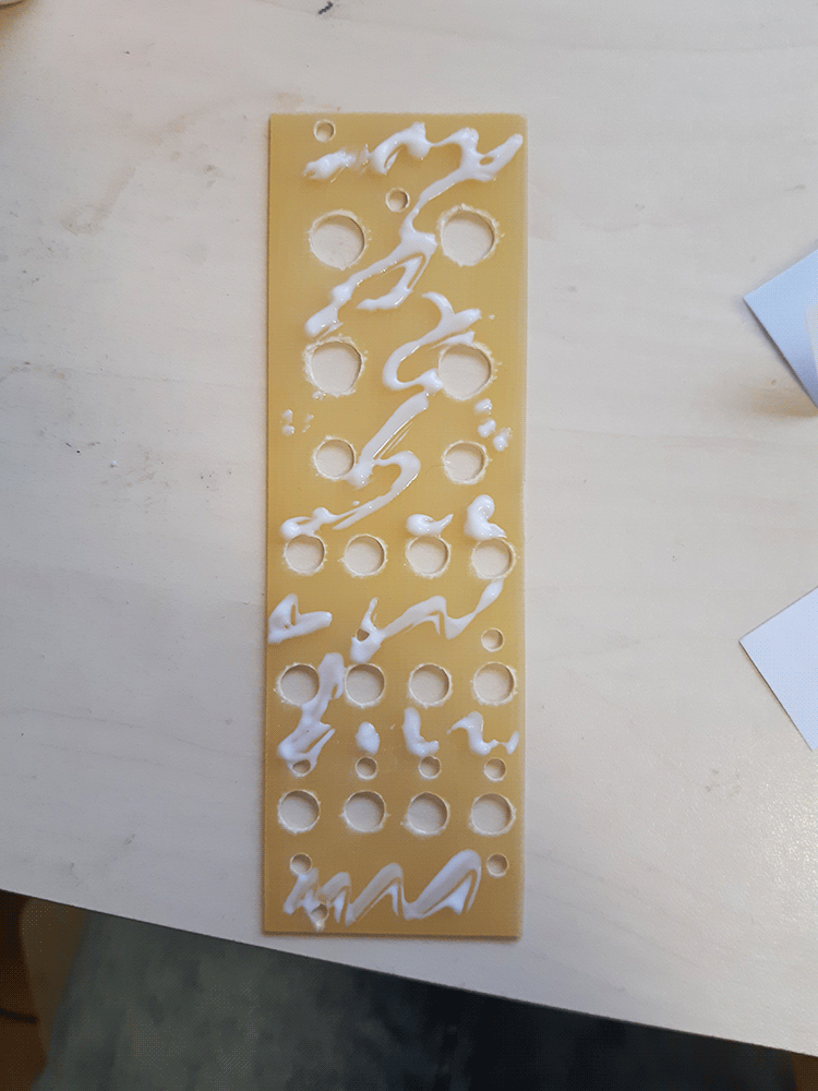
Get some polyvinyl-acryllic glue, aka "white glue" or "office glue". The non-coppered side should receive a thin but visible coat. I put a bunch of big droplets of glue on the board, then use one of the small paper pieces to smear it around evenly, especially paying attention to the panel edges - they peel off unless they receive enough glue. |
 |
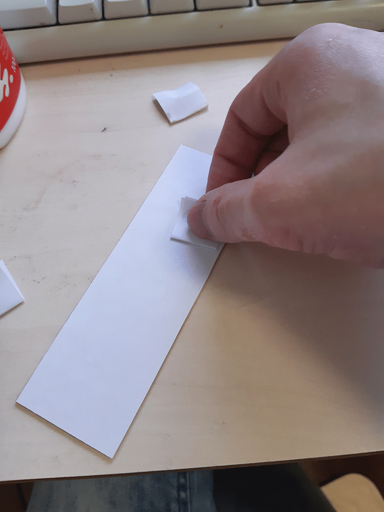
Carefully tent the panel over with the big paper piece. Start bottom to top, gently spreading and it horizontally, only then proceeding further up. The paper should lay as firm and even as possible, without creases or bubbles. After this is done, use a small paper piece to firmly slide against the panel edges multiple times to make sure the paper sticks - doing this with fingers may damage the paperface surface. |
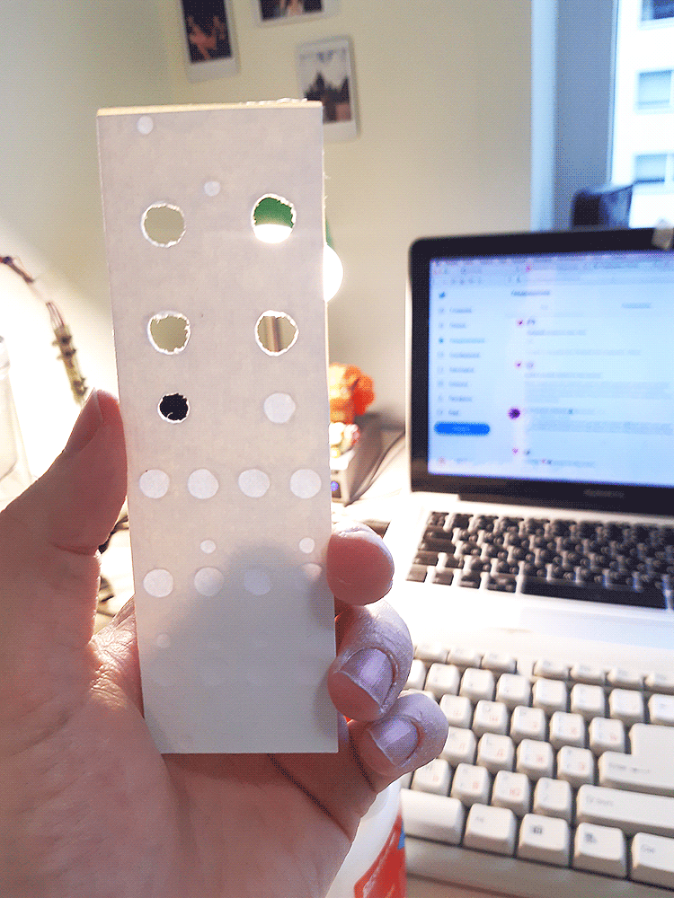 |
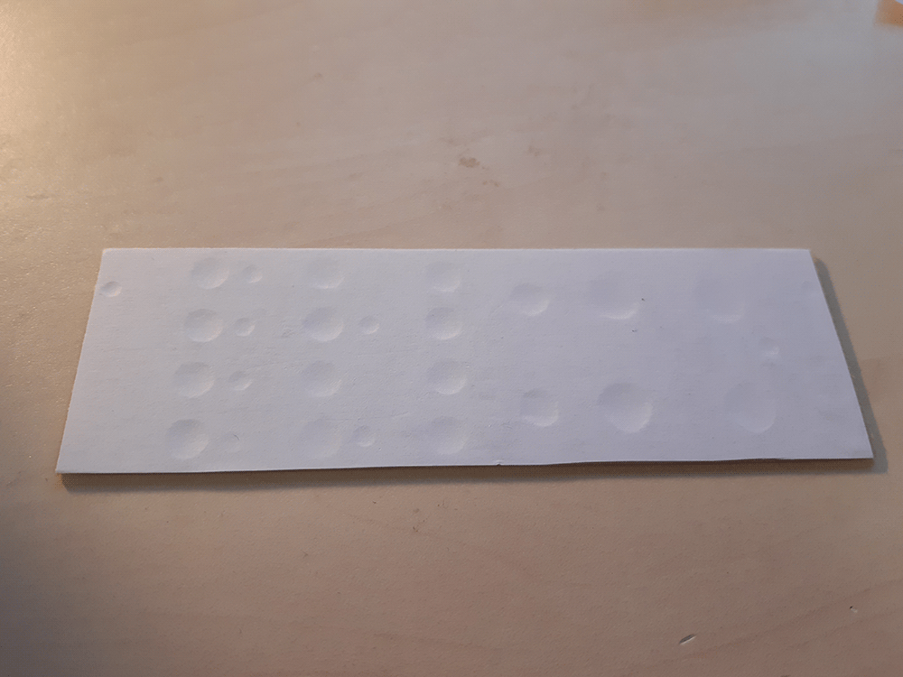
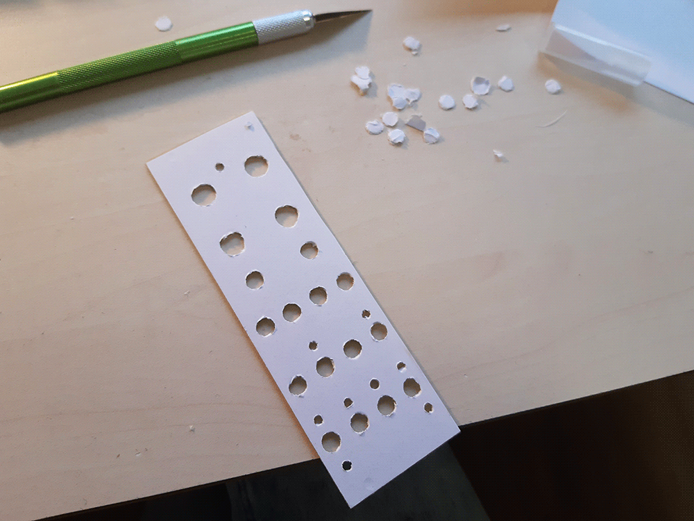
Time to cut the padding and the holes with an exacto knife! Put the panel copper side up (paper down) on a cutting mat and use a sharp exacto knife to run along the panel's contour. The padding should come off easily. If it doesn't - re-cut instead of pulling, or you may tear off some of the actual paperface. Cutting the holes is easier when holding the panel against a light source, as they become visible as light outlines them from behind. Each hole can be done in two cuts: one semi-circle, and then the other, starting about 1mm away from either of the first cut's ends. |
 |
|
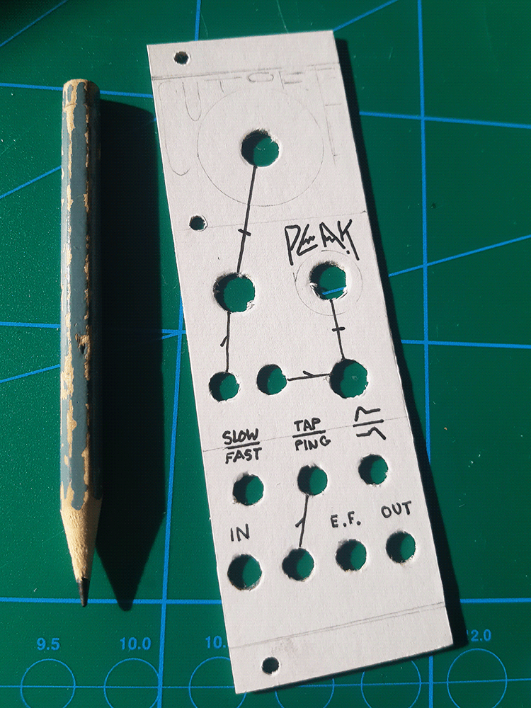 |
Time to sketch up the design! I usually have something in mind before even starting on the panel, but there's always room for experimentation. I like to take the knobs and trace them gently with a pencil, so that the writings don't pathetically crawl under the knobs when you put them on. Then i line the design with a 0.6mm manga marker (the literal model name). I prefer black only, but nothing stops you from using many colours, or even glitter gel pens! |
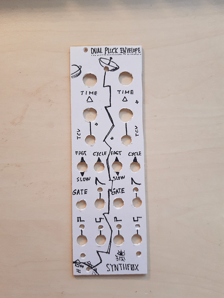 |
Use an eraser to gently remove the pencil sketchings, and voila - the finished product! Done with a limited set of tools, no professional machinery, doable even inside a student dorm (that's where i developed the method!) Have fun! |