NB! This article requires some BARE MINIMAL knowledge of electronics. You should know things like what a capacitor and a potentiometer is, why do we need resistors, and so on. Here, i am explaining how to start with the synthesizers, but for the most basic base, please refer to some other tutorials and videos in the Net - plenty of good ones, better than i could ever do!
Hi, i'm Astro and i've been making modular synths for a while now. While i'm not a master chef of synths, i found out a lot of things during this time, and now feel kind of ready to share my knowledge with people asking how to get into modular synths. Do note that the opinions here are subjective and might (harshly) differ from the ones you probably have, especially if you're some kind of a tried-and-true SDIY veteran. All people have their own ways, and i'm sharing mine. Share yours, too! Anyways, let's get to it.
I want to build a synth, what do i do now?
First of all, don't rush and build huge plans, of course! This is something lots of people do, and then they mess up on their first move, get disappointed, and abandon the idea. Not the way to be. Pick some easy project - even if doesn't look not that interesting, trust me it will be! Atari punk console, triple CD40106 oscillator, or a big muff tone control section are some ideas to begin with - these are simple and fun circuits to build for your modular. More complex stuff will be possible as you progress. Some technical background, especially in electronics, would be really helpful - if you don't have any, i recommend you to read some articles on what current and voltage is, how a resistor affects them, what is a voltage sectionider, and about rc lowpass and highpass filters, some basics on how a BJT and an FET works. The knowledge will stack in your head as you make more projects - but only if you put effort into understanding how a circuit works! You won't gain a lot if you just connect the correct parts.
Secondly, think of what format you want your device to be. What controls, inputs and outputs do you want to have. We are mostly talking modular here, but honestly speaking i advise starting with a standalone box or a guitar pedal. Making a rack is a long adventure that requires some skill. Think of how your project would look like visually. For eurorack that implies sketching up a faceplate (in 'easy mode' the horizontal pitches can be measured as 5mm and the available height of the module can be assumed 110mm), for standalones it's a free choice of things. Remember that your device will have a board - be sure to check out some DIY builds of your kind to get a grasp on how to position boards and controls on a faceplate or inside a casing.
Now you have an idea for a project. That's very good! The only thing remaining to do is well, make it real. The usual flow of making a project real is:
-understanding what is the circuit you are going to build
-testing it on a solderless breadboard
-transferring it to an actual working assembled unit
For step 2 and 3 you will need some parts and tools, which are discussed in the next session. Once you have the idea of what you are making, the understanding of the way it works, and the parts needed to make it, you are pretty much ready to build something - the only thing that is needed is some soldering skills and patience.
List of things i need to start having fun
Buying parts for a project is fine, but my experience tells that in the modern era of online shopping, it's way cheaper and easier to invest into some generic part kits and forget about at least shopping for resistors and capacitors for every single project. The ICs (integral circuits, those tiny spider-like chips) are more project specific, but there are a few you want to stock on, too. But apart from the actual parts, you need some equipment first. Trust me: you WANT to test a circuit on a breadboard before actually soldering it up. If it is a design from the internet - you didn't get how it works, if it's your own - it has errors. All of that is fixed by testing it out on a solderless breadboard first. So for testing i would recommend getting:
2-3 solderless breadboards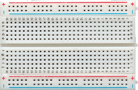
a couple packs of flexible male-to-male breadboard wires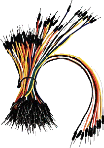
a hard jumper wires kit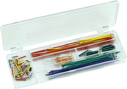
If you have no idea how does a breadboard work - please read it on the internet. There's a bunch of sweet tutorials. You can use ready made solutions for providing power from a euorack synth or a typical guitar pedal PSU to a breadblard, or spend some of the flex wires - just solder them to the contact pads of the power jack, and your breadboard is already powered. Now, of course you'd need some parts to start trying stuff out. I recommend to start with buying:
-a resistor kit (about 1500 pieces, about 20 of each nominal, will do for the start)
-an electrolythic capacitor kit
-a multilayer ceramic capacitor kit (the fuller the better)
-a bag of 2n3904 (common NPN) transistors
-a bag of 2n3906 (common PNP) transistors
-a bag of 1n4148 diodes (also very common)
-a bag of 3mm LEDs of your favorite colour
-finally, a bag of connectors of choice.
The connectors are a whole topic for discussion here. I definitely prefer banana jacks over anything, but i also build my own prototyping station to use them, which is maybe not something a beginner would pull off right from the start, so i definitely recommend starting with common standard 3.5mm mono audio jacks. Please learn about your preferred connector - where the signal and (if exists) the ground terminal is, what is a normalised contact (for 3.5 and 1/4inch jacks). It was my very common mistake to confuse the terminals and i fried my headphones because of it once.
A very good testing move would be to take a black and a coloured flex wire, and solder the black one to the connector's ground, and the coloured to connector's signal. This way you can connect this jack directly to a breadboard and input or output signals through it! Just plug the ground wire to breadboard's ground rail, and the signal to whichever point you want to listen/plug in to. NB! Outputting audio from a breadboard to your headphones is a whole interesting topic, so i recommend using a sound amplifier inbetween. Always use 100-560 ohms of resistance at the sound output if you are not using a decent quality amp with a volume control.
Having this much parts, the testing jacks, and the power supply, you already can build a guitar fuzz pedal, or test out various RC filters, on your breadboard. However, a lot of projects use Integral Circuits (ICs) - those are basically chips which have a ready to use, off the shelf circuit inside. Your job is to power it, and you can start using its functions! (the + is usually labeled VCC, and ground is either VEE, VSS or GND - but always refer to the document called 'datasheet', it has all the data on the chip you're using)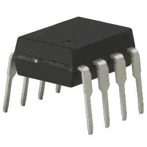
ICs vary from Operational Amplifiers (op-amps) which have tons of different applications - with appropriate circuit around them, they can mix sound, compare CVs, amplify external signals, and many many more - to chips like CD4017, whose single application is being a literal ready-made gate step sequencer, feed it a clock signal and it starts. Some ICs are very common in synthesizer world, though, so i will list them - and you better buy a few, they're not that expensive.
The essentials: you will use these A LOT. Get a bunch.
TL072 - a common dual op amp
TL074 - same as above, but 4 in one package
LM358 - also an op amp, but unlike 07X's JFET inputs, has a true differential input required by some builds
More old-school ICs found in envelopes, VCAs, VCFs, VCOs:
CD4007 - dual complementary MOSFET pair and an inverter
CA3080 - a current amplifier, essential part of a classic VCF and VCA
LM3600 or LM3700 - almost every Serge module has these
CMOS logic, xtremely cheap and fun to play with:
CD40106 - 6 schmidt triggers in one package, can literally be six oscillators, or even VCOs
CD4013 - a dual D-trigger, basically a bit of memory which you can read and write. Oscillators + it = harsh noise!
CD4040 - a binary sectionider. Handy for off-shelf suboctave generator or clock sectionider.
CD4030 - a XOR gate: something you can't get with transistors easily. 2 oscillators + it also = funny harsh noise
Some fun audio ICs - not mandatory at all, but may be fun to try out:
PT2399 - an off-shelf delay circuit. Sounds like crap to audiophile ears, which is a pro.
LM386 - a speaker driver. Also a crap piezo amp and an excellent sh!t distortion.
Out of all these, the only ones that are truly necessary almost everywhere are the ones in the first section, the op amps. Everything else is user choice, but i really encourage you to check out what a lunetta synthesizer is, grab some logic ICs, and play with them - it's very beginner friendly and runs off a uniploar power supply.
Oh, and also! Don't be greedy and buy a bunch of IC sockets - DIL8, DIL14, DIL16. DIL means Dual In-Line package, and the number means how many legs does the sockets have. While on breadboarding stage, these won't make any sense, but just believe me - when soldering up a final version, you are better off soldering in a socket first, and then just plugging an IC into it. If it is wrong, faulty, or burns for some reason, you can just pop it out with tweezers and click in a new one. No IC desoldering trouble!
All this stuff can be bought on Aliexpress for cheap, or at your local radioelectronics store for a few multiples of that 'cheap'. Some Aliexpress listings that i personally ordered and received in full operable condition can be found here.
Actually making a working unit
So you got all the parts, got used to breadboard testing and the thing you are working on is perfectly functional and you are happy about it. Now it is time to make it into a functional unit! As i said earlier, i heavily advise to make a standalone box as your first project - be it an atari punk console, a CD40106 VCO box, a passive volume knob, or anything else. If you already have a rack synthesizer - then you can try making a rack module, but be sure to comply with all the standards then! If you don't - start building a rack after you try some standalones. So take your box, plate, panel, or whatever you want to put your device in, and mark all of the places that you want the controls to be at with a sharpie. There are various techniques of how to do it more preciesely, but for now simply using a ruler will do. Then take a hole marking punch (or an old unneeded rusty drill bit) and a hammer, and gently, carefully, but not lightly punch the holes you marked. Now you can take a drill, align the correct drill bit to the prepared pre-punched hole, and drill with confidence that the drill won't drift away, as long as you hold it vertically and apply pressure carefully and steadily. Main hint - do not rush while making faceplates or preparing boxes: i know that you want to finish the build as soon as possible, but trust me - better spend 10 more minutes on preciese drilling than have all the holes offset to god-knows-where. After this, you will wind up with a housing ready for filling up the actual circuit.
A metal box predrpilled for a guitar pedal layout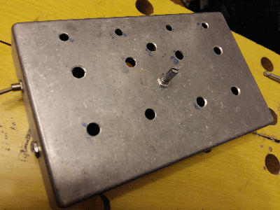
some drilled Eurorack DIY faceplates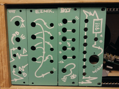
Anyways, after you prepared the housing for your device - it's time to make a board. Some devices don't really require one - Eurorack passive mults and my own passive utilities can be built by just soldering some wires and parts directly to jacks behind the faceplate. But anything more complex than that is best done on a circuit board. It will require patience and soldering skills. If you didn't by now - learn how to solder in the internet - there's a ton of good videos on it. But this brings us to another never ending battle, which is...
Protoboards VS Etched Boards
Funnily enough, i see the SDIY community sectionided into two main camps - the PCB Purists and the Protoboard Punks. Rarely do i encounter a person who uses both methods. Yet they both have huge pro's and con's.
Basically a protoboard is a board that looks something like the one below. There is a hell ton of protoboards, but this one is so far the most convenient, and is called the Veroboard. It has holes spaced 2.54mm apart (standard DIP IC leg spacing) and has traces running vertically. You can cut traces with a 4mm drill bit - just lightly drill on the hole you want a break to be at from the copper side, just enough to scrape the copper away - and the line is now two lines. By cutting lines at correct places, and connecting the elements on correct lines, you can re-create a circuit you made on a solderless protoboard on the veroboard. In fact, a solderless protoboard is just a convenient veroboard with a gap in the middle to acoomodate for DIP ICs. It can be tedious to do all the wiring and trace cutting on it, but if you did something wrong - you can always step back and re-do everything - there can be no hotfix if the whole device is one big hotfix.
Here's the copper side of a veroboard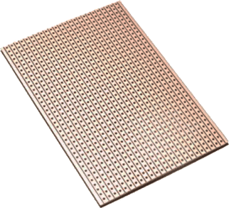
a complete project made on a veroboard. Note how parts are mounted on the other, non-coppered side!
Img (c) this blog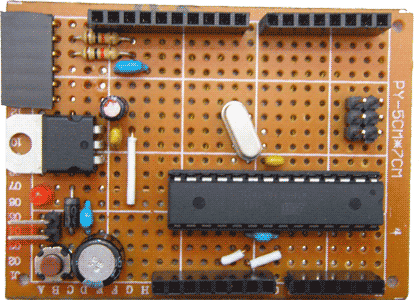
Bottom (copper) side of some other veroboard-made project.
Note how some pads are intentionally scraped up and break the lines.
Also notice the plastic standoffs! Important for mounting the board into casing!
Img (c) there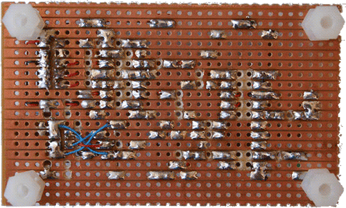
An etched board, or PCB (Printed Circuit Board), however, should be made by you. It starts with a clad board - same as the veroboard above, but it has no traces: just an even copper surface without any interruptions. Then, there is various ways of etching a pattern on it: one is - making a black stencil on a transparent foil (available for purchase in A4 sheets), laminating a sheet of photoresistive foil the clad board, then exposing it to a UV light through the stencil, developing it in a calcined soda soultion - the exposed photoresist will stay on, and the parts blocked by the stencil would go away - and then throwing it into the etching liquid. Usually that is ferrum chloride. It would etch out the parts not covered by photoresyst. Then the board is once again thrown into soda - caustic this time, and the exposed photoresist goes off. Beautiful!
Now the only thing you need to do is take a very small hand drill or a dremel with 0.7mm drill bits (of course you have all that) and drill out every hole through which a component should be put and soldered up, and you're done! If that sounds complex and overkill to you - you are damn right, it is! And the fun part of it is that i was starting with it and was passionately hating veroboards as a beginner, and this was a CRUCIAL MISTAKE! Don't do this! PCBs have a huge bonus compared to protoboards: you can make as many same ones as you want without much hassle, they can have way more ergonomic component placements and trace shapes than you could ever make on a protoboard, and they look neat. But! They require you to know a computer program, like EagleCAD, to make a circuit, and the whole process is a very expensive and hard task. At one point it will be a necessity - but for beginner projects it most definitely is NOT. At one point you will want to make something more than a mixer or a distortion, and then you can enter this hellzone, but entering the whole SDIY topic is definitely easier with protoboards.
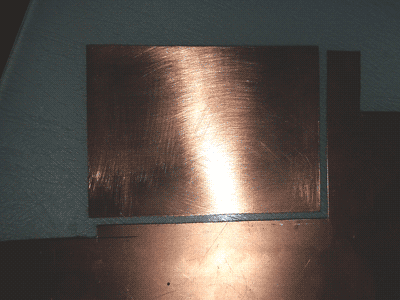
Here's a clad board cut from a sheet of FR-4 coppered textolyte
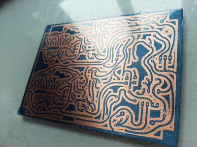
Here it has the developed photoresist on it: you can see the copper through the washed-out trace outlines.
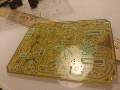
The PCB is etched, the holes are drilled and on the other, uncoppered side, some basic placement is drawn with a marker
Finished PCB project
Conclusion: this is a page for beginners' read, and to beginners i recommend using veroboards or some other kind of protoboards. If you want to bite the bullet and etch boards straight off - your choice, but if i didn't hate veroboards back in days, i would gain way more experience way quicker. In advanced SDIY life, often a printed circuit board is a preferred choice - and you will find some PCB stencils here on the website, too.
Putting it all together
Once you have a ready casing and a finished board, the only thing left to do is to put them together! Grab some wire, your potentiometers, switches, and whatnot, and start connecting them to the correct points on the board. I heavily recommend to not solder any pots or switches diretcly to the veroboard - i know it is one of the common practices, but in my experience it usually makes stuff messier and harder to handle or hotfix. Usually i take some wire and cut as many pieces as i need, strip them at both ends, then grab them in fives, take some flux (i prefer the liquid one, with a tiny brush like in nail polish), put it on all 5 endings and solder some solder on those tips. Then i flip the wires and do the same to the other end of the wire. Then take your jacks, potentiometers and switches, and connect the wires to the pins you're going to use. Finally, solder in the components to places they should go to. Easy! The hardest part is not to mess up with which wire is what - so be careful and, as always, never rush. Now just screw the control elements to the casing, secure the board inside the casing (you left some place for at least two standoffs on the board and some place to screw it to on the casing, didn't you? you should) and you're all done! Connect it to the power and watch it burn and explode as you try to think of what happened c:
No, really, in most cases the thing you just made won't start from the first attempt. The cause may be pretty much anything from a short circuit on the veroboard to just wrong circuit design. 'Debugging' your circuit can be tedious and here's where a multimeter comes to the scene! I heavily advise you to get a decent one - no need for expensive stuff, but no $3 mul's either. The steps i usually take to troubleshoot a veroboard circuit is:
-Disconnect the circuit from any power supply
-Check connection between +V and Ground. There should NOT be a connection, having one means a PSU short circuit!
-Check connection between ICs + power pin and the + of the power input jack/header
-Check connection between iCs ground and power input's ground
-All good? Then check the connection between each of adjacent veroboard strips - especially the places with your soldering. Sometimes a tiny part of the solder blob would be touching the nearby line, ruining everything.
-Finally, if there are no short circuits and bad soldering, start comparing each connection on the veroboard with your schematic. Most likely you have an error in either the layout, or the schematic itself is faulty.
For harder and more complex projects, another order of assembly might be better - to screw on the control elements (pots, switches, jacks) on the casing or the front panel first, make all the necessary connections between them, and then connect them to the board with wires. It's convenient when on the bench you have at least something like an 8-step CV sequencer, or a 4-channel mixer, which is already a few steps ahead from the beginner's first project.
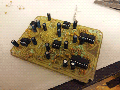
This is my Quad Wavefolder, built on a veroboard. Oh, the pile of wires between the board and the panel! This is not a beginner grade project, but you get the idea.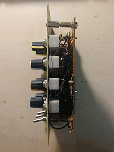
The back of the same module - not that much soldering, if you think of it.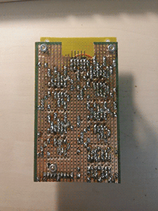
To conclude all this..
So yeah, this article is pretty much the bare minimum overview of how can you get from 'i want to make a synth' to actually making something. To wrap things up, i want to say what i said up there in the beginning: if you are reading this article because you ARE a beginner and this IS your first sound-related project, 1. don't go for making complex stuff: choose something simple and quick to make. It will be a whole bunch of fun to troubleshoot anyways. And 2. if you don't have a modular rack as of now - don't go building one yourself. It's rather complicated, and i heavily advise to train on fun little standalones first. Spend some 'initial capital' on basic parts: it will be cheaper than shopping for each project's full bill of materials insectionidually. Don't rush while making your boards, faceplates and casings: grab some tea, do one thing at a time, and root for the quality of your resulting device, not for the time spent on it. Don't hate "crap DIY" solutions like veroboards and solderless breadboard prototyping: even though there is a certain (dumb) stigma on them in some places, those ARE the hting that help you level-up in SDIY. Be patient when debugging the circuit, and if it makes you rage out - frequent case with me - drop it for at least some hours. It wil work eventually, with your clear and refreshed mind. Ok? Good. Now get going!
If you have any suggestions, found any typos, or have comments or questions about the article, get to me about it to analogpatch@gmail.com. Thanks!