About
Passive Tools 1 was created out of boredom. I was just sitting and thinking to myself "hey, i gotta make some multiplies for my Eurorack system" - but then, why should one make multiples, when in the same HP and in the same passive way, they could have some FUNCTIONALITY? So i challenged myself to think of something very powerful for a 3HP passive module - and i created this.
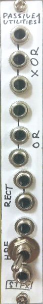
Passive Tools 1 (i know it says "utilities" on the paperface, i renamed it later - 'tools' sounds sharper) has 4 submodules on board:
~ XOR-like Wave Smasher (XOR)
~ Diode Maximum Detector (OR)
~ Diode Half-Wave Rectifier (RECT)
~ Switch-adjusted Passive High Pass Filter (HPF)
the first two are cool both for CVs and audio, especially the XOR thing - it doesn't do exactly what it says, but the way it merges to signals into one is kind of ringmodulator-ish, except not really, and it sounds really cool! The OR part does same thing as your Maths' OR output, it outputs the voltage-highest of the two signals. except when it does not. The rectifier is a Classic, just put your sinewave into it to get a fancy half-sinewave half-silence - basically it eliminates the negative part of the signal. Can be handy sometimes. The VERY handy part is the HPF - the switch (should be a 3 position on-off-on!) changes the cutoff frequency, and while it's just a passive HPF, sometimes it's exactly what you miss - harmonics-rich waves tend to overlap in bass layers, so it's a very good sound-fitting tool.
I built it in half an hour without any preparations and no boards - it's just components soldered between jacks - and it works like a charm and does lots of good, so i consider this as a very good beginner's DIY project.
Schematic
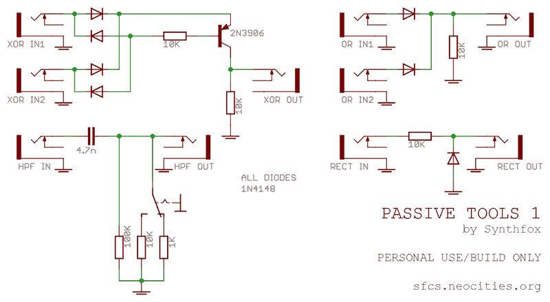
Not much to tell you about this schematic. It's inspired by common diode logic circuits. XOR resembles a ringmod in a way - it's a full bridge rectifier shaking the transistor with its outputs. OR is a classic diode OR gate - or a diode 'mixer', it will eliminate the negative side of the resulting signal, which is the highest voltage of the two input signals' voltages. RECT is also a very common circuit - the diode takes the negative part of the signal to the ground, and the positive part passes through. HPF is a classic, simplistic first order resistor-capacitor filter with three settings - the only thing i did here is chose smart cutoff frequencies for it to be useful in mixing audio inside the system!
Media
Two doepfer A-110 VCOs (tri and sine) passed through the XOR section - has a semi-ringmod trashpunk feel to it and stars consonating on nice intervals.
Single A-110 (tri), pitch CV'd by two LFOs, one slow and bipolar (-10v to 10v) and the other fast and unipolar (0 to 5v) combined throguh the OR section. Note how with the rise of the slow one, the fast one's peak become less and less high, and eventually the slow lfo exceeds the fast lfo's amplitude and sends the VCO to a long bend, and as it go down, the fast LFO kicks back in.
Noise (Senor Serge Generator white output) passed through the HPF section, toggling of the switch showcasing three different cutoff settings.
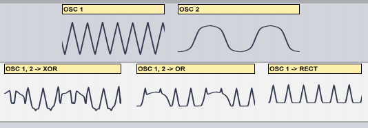
Some waves recorded into Ableton to show how they look like! On the top are the 2 original VCO waves, below are results of their mixtures through XOR, OR, and the first VCO through the RECT stage.