About
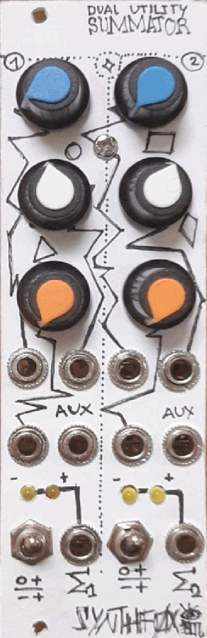
A handy universal voltage processor that does exactly what it says on the lid: sums voltages. It has 2 identical halves. Each has 4 inputs, 3 of which have a dedicated attenuator. A switch selects either the unipolar (0 to maximum amplitude) or the bipolar (inverted maximum amplitude to maximum amplitude) action. Top input has a positive voltage normalized to it, so when nothing is patched into it, it acts as an offset generator. This is a very typical and classic module with all the switches and normalizations you would need for happy patching. Everyone must have one like this!
UPD 26 Oct 2021: there's somethnig about me pulling off complicated schematics no problem, but failing with simple stuff like this. The schematic was somewhat wrong - input 4 would be grounded in uniploar mode... i truly hope no one built anything by the old schematic. If you did: sorry! I updated it just now.
UPD 5 JUL 2022: finally designed a good LED driver for this purpose. No more signal loss at the output! The new design is for the FOXYSTEM rack, and uses this one as its base. Check here and slap it instead of the bare LEDs in this design, if you wish for more precise performance. This one still works, though, just not as nicely.
Schematic
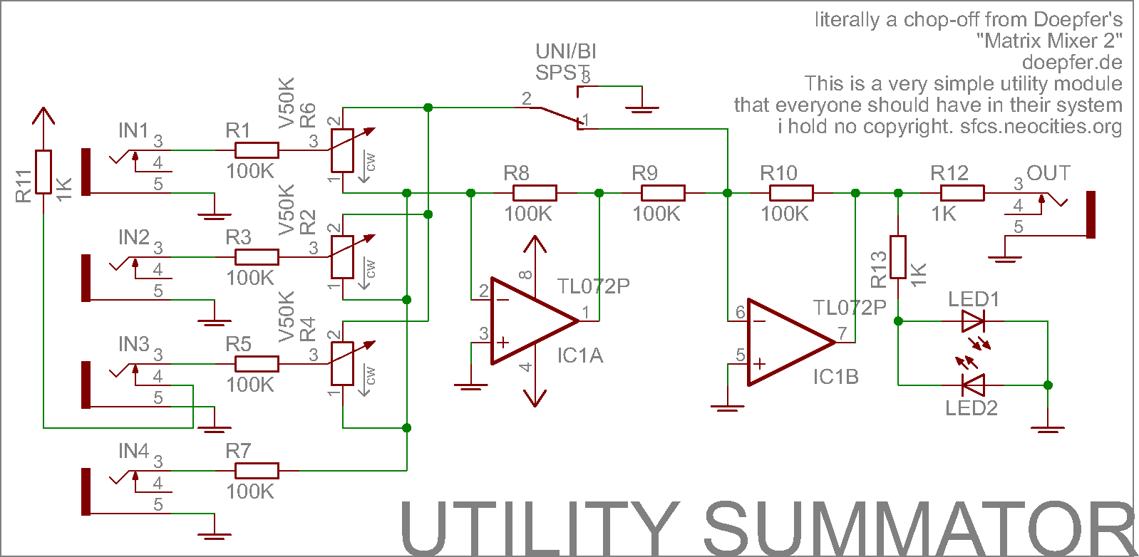
The schematic is plain simple, and is basically a tore-down version of Doepfer's "Matrix Mixer II", an example circuit from their DIY tutorials page. That page is very nifty, if you're new to SDIY - i recommend to read it and keep it in mind. Also, the operation is extremely standard and simple. Hence i hold no copyright to the circuit design.
The op amps act as summators with -1 gain. The potentiometers do a different thing depending on the switch position. They set either how much of the signal goes to the ground and how much of it goes to the first op amp (and gets summed with other signals and double-inverted), so, unipolar action, if the switch connects to the ground.
If the switch connects to the second op-amp, the potentiometer sets how much signal goes to the first op amp (and gets double inverted), and how much to the second one directly (gets inverted just one time). Feeding these 2 paths equal voltage will make the output stay at 0, as the inverted and non-inverted versions cancel each other. The more you go to one side or another, the more inverted or uninverted signal you get. So, bipolar action - like an attenuverter.
The fourth, auxillary input, is always uninverted even if the module is in biploar operation mode, which allows for some constant offsets, summator chaining and perfoemance tricks. +12V is normalized to the third input, making it an offset dial if nothing is patched in.
This is a very handy universal utility, and i suggest you make at least a dual version like i did, if not a quad one (actual matrix mixer possibility here!)
LED notice: the fancy dual LED indicator is a bit current hungry, so it will introduce a slight-yet-very-obvious voltage drop to the output signal. This means you can't plug in a 1v/o quantised sequence and expect it to be intact on the output. I don't care all that much, but you can fix that by doing both of these two things: 1. use another op-amp as a voltage follower behind the LEDs, and 2. put a 10K trimmer in series with R10 to amplify the signal just a little, and then precisely calibrate it: put a 1v/o quantised signal to input 4, put the summator output to a 1v/o-tuned VCO and turn the trimmer so the VCO plays in tune..
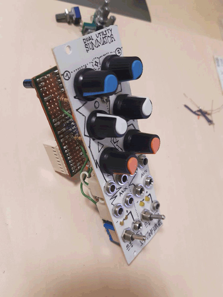
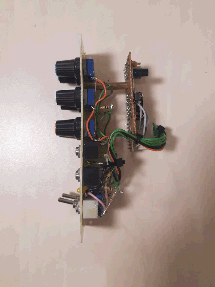
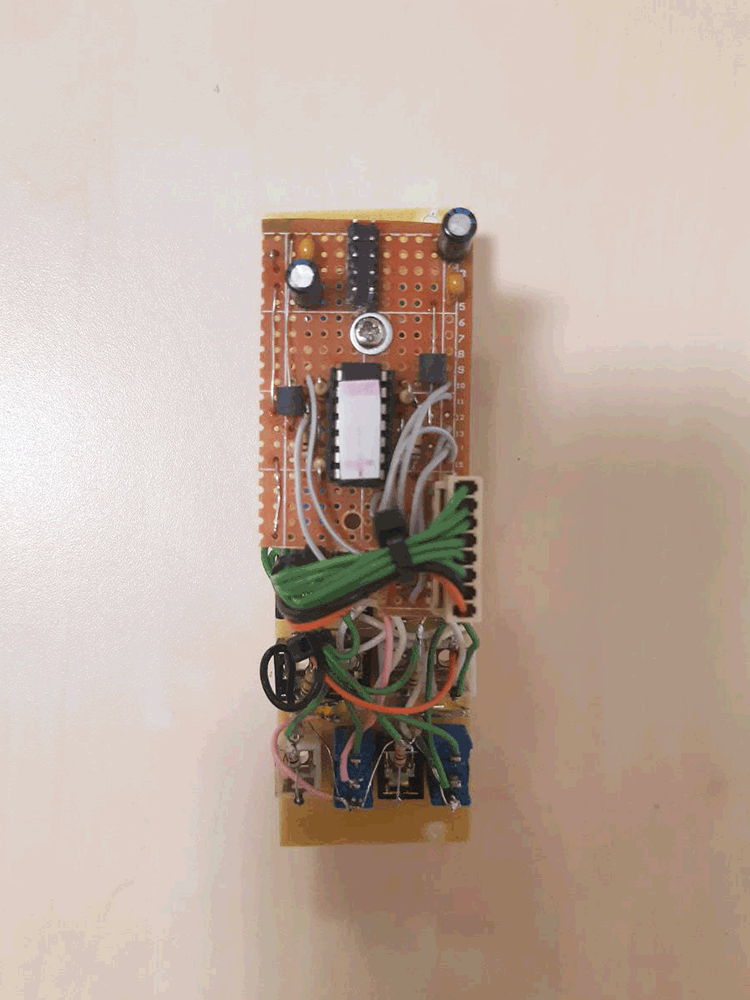
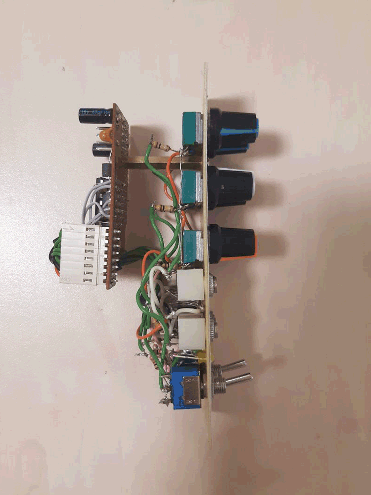
Pictures