About
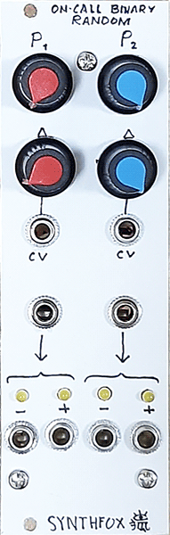
On-Call Binary Random is a dual random event generator. It expects a gate, although will gladly attempt to convert any input into one, and once the gate fires - it samples a random binary value: either 0 or 12v, and hold it until the next gate is fired. So you can think of it as of a binary sample-and-hold with noise pre-patched as the sampling source. The interesting part is the probability control: the noise that is sampled is "binarized" fom actual transistor white noise with a comparator, and the comparing threshold - defined by the probability (P) knob and the associated CV input - will set a probability of the "binarized" noise being high* at the moment of sampling. Each of the two such units have paired outputs: positive and negative, which are inverts of each other.
This module can be used to create interesting probabilistic gate patterns, introduce random events which keep up to the general rhythm, or even generate noisy SFX!
*it actually determines the probability of getting a logic low at the 4013 "binary sample-hold" input, but the inverted and non-inverted outputs of the 4013 are swapped roles on the faceplate, so virtually the more clockwise the P knob goes, the more probable is + sampling high and - sampling low.
Schematic
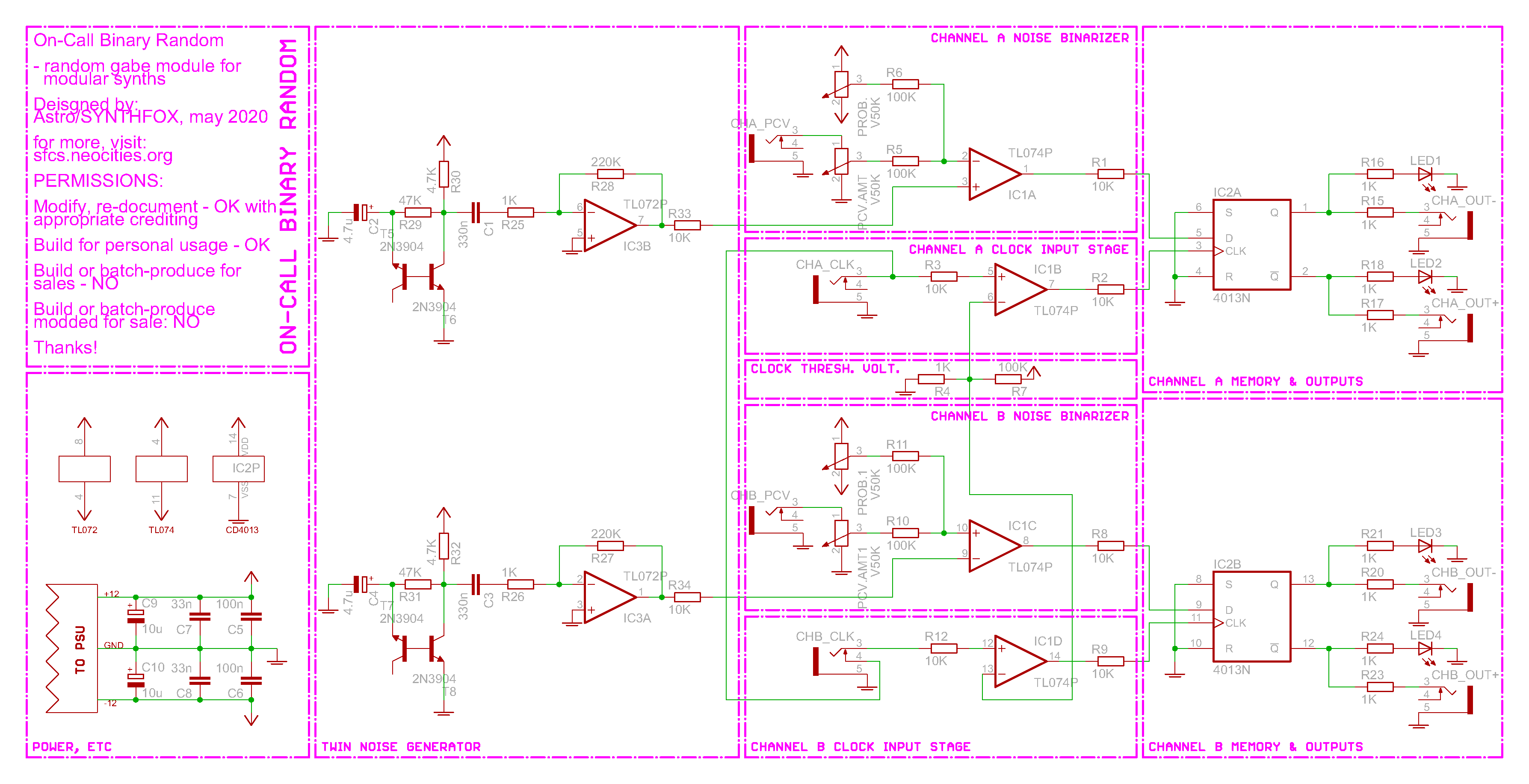
The schematic is widely copied from the Shift Core Generator: the noise generator, noise binarizer and clock input stage are almost the same. White noise is generated with a reverse-breakdown bipolar junction transistor, amplified with another BJT, then amplified yet again with a gain of about 220 by an op-amp. There are two such generators on the board for completely unrelated random gates, one per 'channel'. The noise is then passed through another op-amp set up as a comparator, it's other (non-inverting) input has a sum of the probability value knob and the attenuated probability cv put to it. The resulting output is a pulsewave-ized noise which only has 2 states, and the relation between them is controllable with a knob and the CV.
The clock input stage is also a comparator - it compares the clock input signal with a small voltage, making it usable with both logic gates, AC and DC signals of audio and CV rate.
The rest of the work is handled by one of my favourite CMOS chips ever - the glorious CD4013 dual flip-flop. Its set and reset pins are tied to ground - we don't need them in this operation. Clock in is fed with the post-comparator clock signal, and our binary noise goes to the data in. At the rising edge on the clock pin, it will sample whichever logic value is on the data pin, output it on Q output and its inverse on the !Q output. On the comparator for noise, we have noise going to the + input and the probability threshold sum to the - input. The output can be described as "if noise voltage is more than threshold voltage, output logic high, if noise voltage is less than the threshold voltage, output logic low". Because of this, the more we raise the threshold value, the more rare will be the case of noise voltage being higher than it, the more logic lows we get at the output. For this reason, the Q and !Q outputs are - and + outputs on the faceplate respectively: we just pretend that the inverted version is the original, and vice versa. With this, as we raise the threshold, the more lows we get on 4013 data input, the more highs we get at the inverted 4013 output, which is labelled + or non-inverted on the plate. Tricky, but - everything to make it work as expected!
Media
Basic sweep of the probability knob up and down, while the module is being gated by a very fast clock. The - output is triggering a filter percussion sound. Note how it gets a bit more dense, then we get way less hits at the middle of the recording, as we reach the full clockwise position, and then the density of the taps grows back as i come close to the center, then to a more slight decrease towards the negative rail.
This module is very good friends with its older sister Shift Core Generator! Here, the SCG N+1 Out is controlling a VCO's pitch and clocks one side of the On-Call Binary Random. The side's output is fed into the SCG Data input - so the probability setting is now controlling how probable is it to write a 1 to the CGS's shift core. An LFO is put on it, and the same LFO controls the VCO's volume prior to passing it through a Quad Wavefolder. As a result, when the sound is most open, we write the most 1s to the shift core, so we're also getting higher tones as well! Likewise, when the timbre is more dull, we get only a few lower notes rolling around.
Using the Doepfer QVCO as a clock source and playing around with the probability setting, putting an LFO in it eventually. Leads to some gameboy-esque noise effect sounds. Very musically useful with a VCA and a pluck envelope for a snaredrum, or a VCF and a fluctuating random voltage for glitchy arcadepunk seashore SFX.
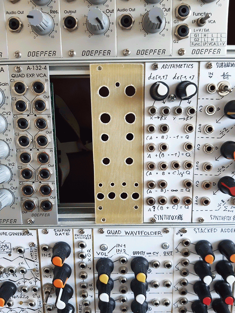
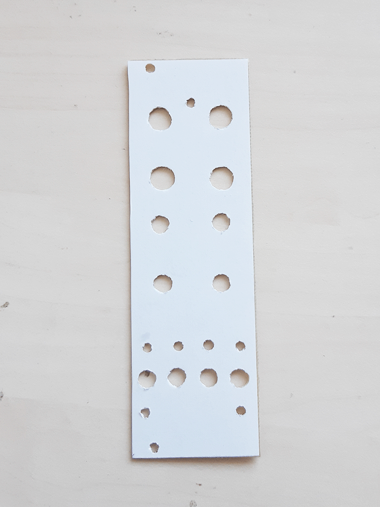
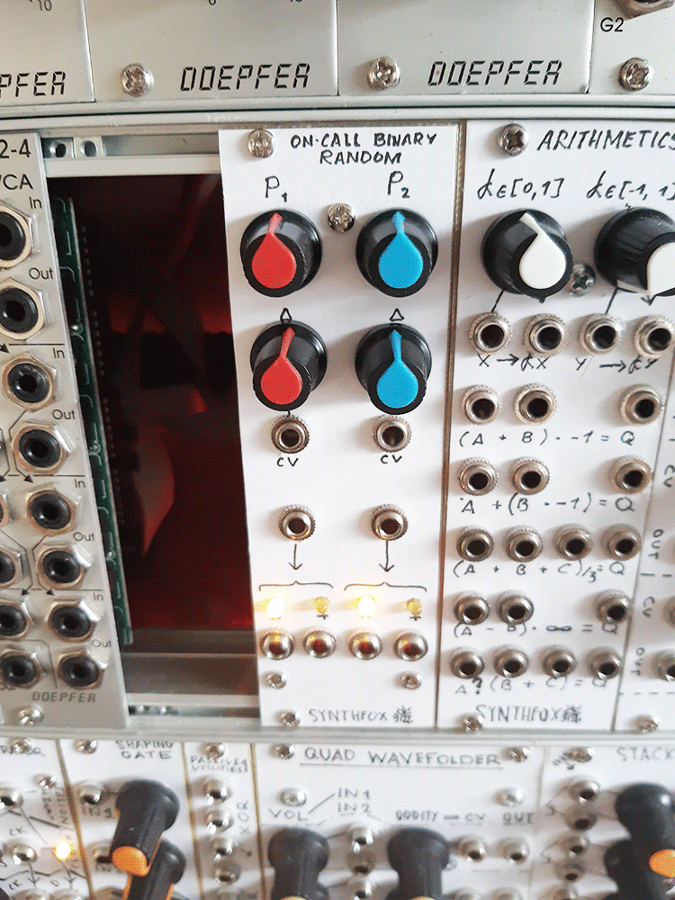
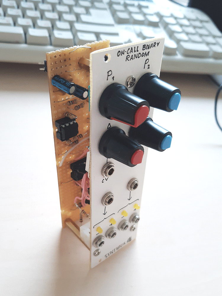
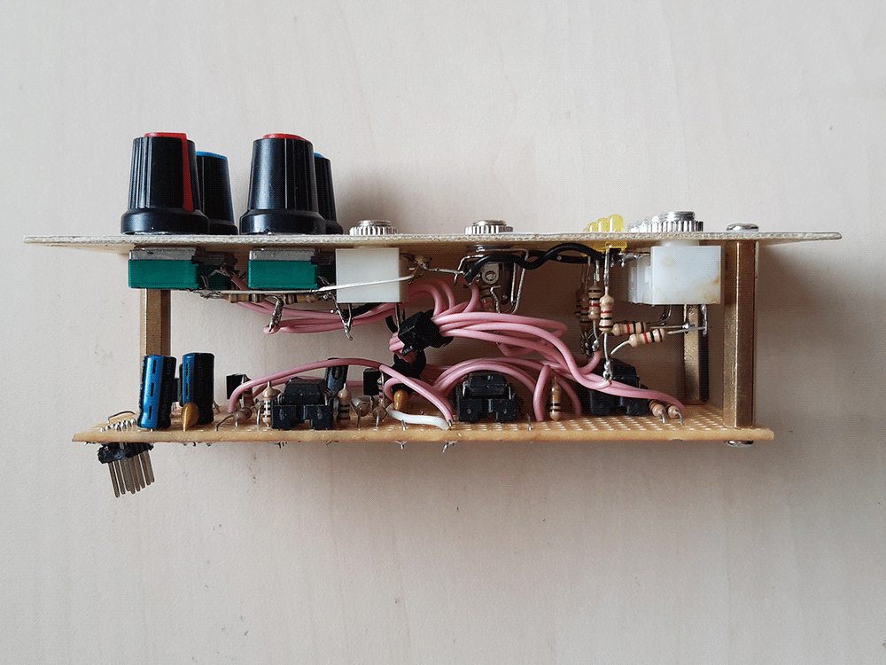
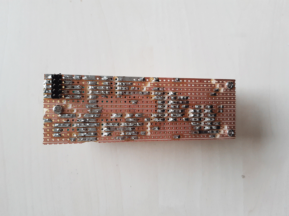
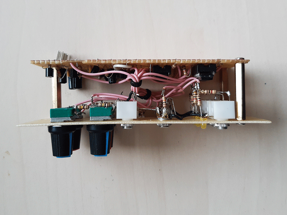
Pictures